Viscoelastic Beam Properties of a TRAC Boom
This tutorial shows how to calculate cross-sectional properties of the TRAC boom with given dimensions and material properties using SwiftComp 1.3 and PreVABS.
Flattened height: 45 mm, Web height: 6mm, Subtended angle: 90 degree, Ply thickness: 0.058 mm,
Radius of the flange (curved part): 24.85 mm,
Layup: 45/-45. The layup sequence is along with the direction pointing to the center of flange(Blue arrow).
Material properties
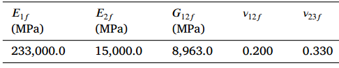 Fiber properties defined as transversely isotropic elastic
The matrix properties are given by means of the Prony coefficients presented in the table below and following the formulation of Figure 1. In addition, we will consider that the matrix has a constant Poisson’s ratio equal to 0.33.
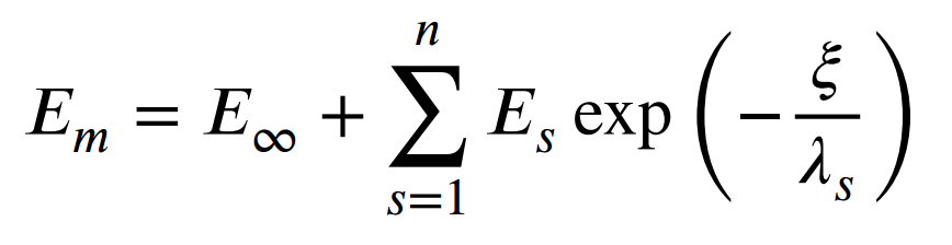 Definition of the Young modulus of the resin
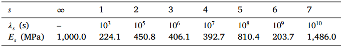 Prony coefficients and relaxation times for the matrix
We will use a square pack 2D SG with fiber volume fraction equal to vf = 0.64.
Software Used
In this tutorial we will use Abaqus CAE with the Abaqus SwiftComp GUI plug-in. Abaqus CAE will be used to GUI to define the time-dependent material properties and to run the viscoelastic homogenization. SwiftComp will run in the background.
Solution Procedure
The steps required to compute the effective viscoelastic properties using Abaqus SwiftComp GUI are as follows.
# Step 1. We define the material properties in global coordinate system. We click on Materials in Abaqus CAE and define the Fiber properties by means of the engineering constants and click “Ok”.
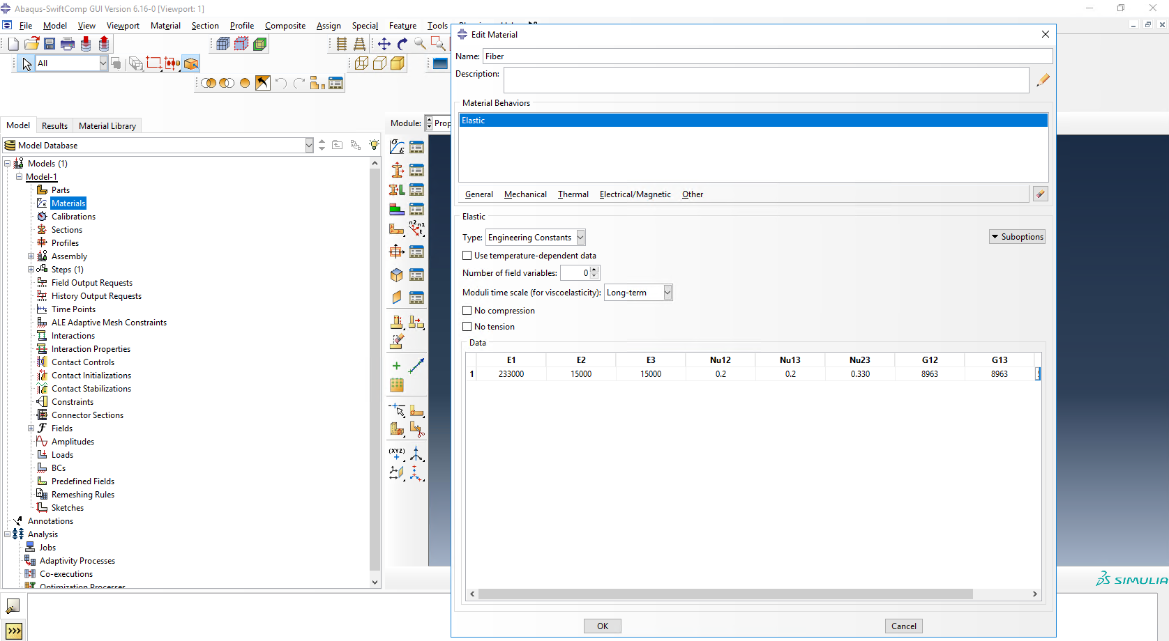 Definition of the fiber properties
# Step 2. Within the Materials of Abaqus CAE, we create a dummy material called “Matrix”. Please note that we will not define the Prony coefficients of the resin using the Abaqus SwiftComp GUI in the next step.
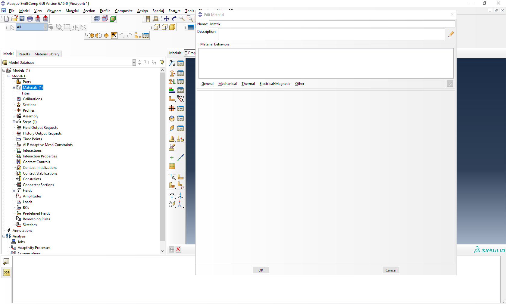 Creation of the dummy material for the matrix
# Step 3. In the Abaqus SwiftComp GUI menu, we click on Input Time-Dependent Properties. We select “Prony Coefficients” and “Viscoelastic” in the Method & Analysis section. We pick “Matrix” as the Material to be modified in the drop down menu. Then, we input the relaxed Young modulus, Poisson’s ratio and the Prony coefficients following the equation presented above. Finally, we click “Ok”.
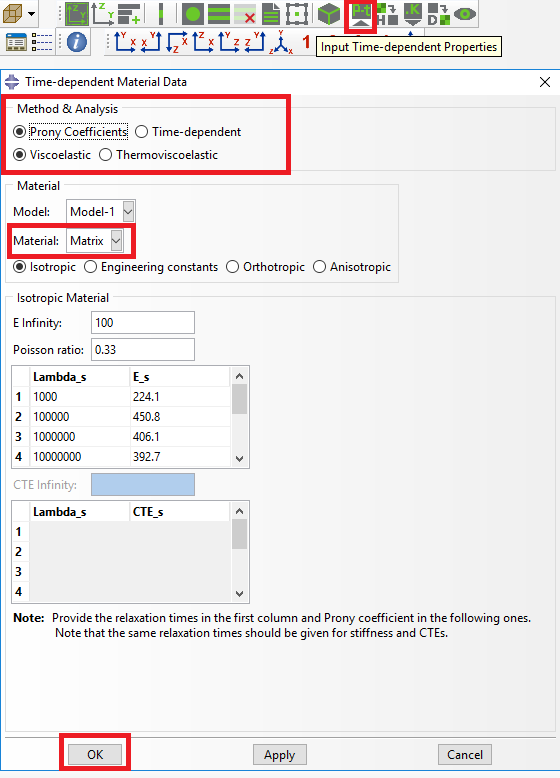 Definition of the matrix Prony coefficients
# Step 4. From the default the Abaqus SwiftComp GUI SGs, we pick the 2D Structure Genome with Square pack. We input the fiber volume fraction, define the approximate global mesh size, and click “Ok”. A square pack microstructure will be automatically generated.
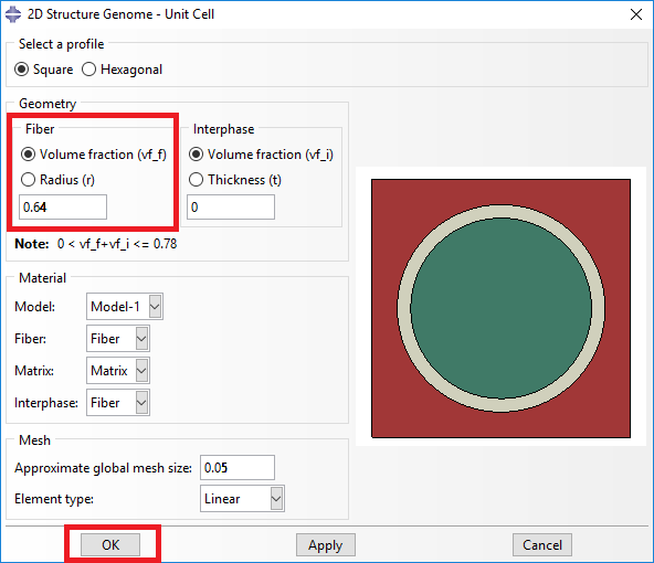 Definition of the 2D SG square pack microstructure
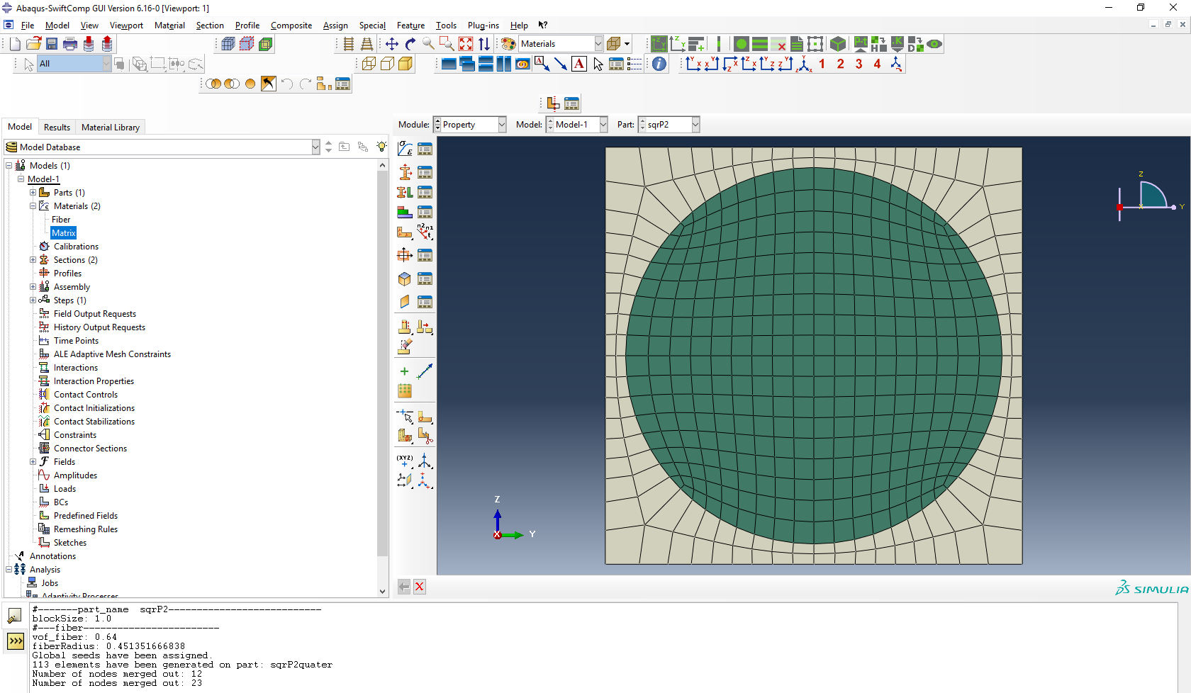 2D SG square pack microstructure
# Step 5. Now, we will compute the effective viscoelastic properties. To do so, we click on Homogenization and select Viscoelastic in Analysis Type. In the Viscoelastic/Thermoviscoelastic Analysis section, we define the range of the time (i.e. Initial time” and Final time”) in which we want to output the effective properties as well as the frequency (i.e. Time increment” defined in decades).
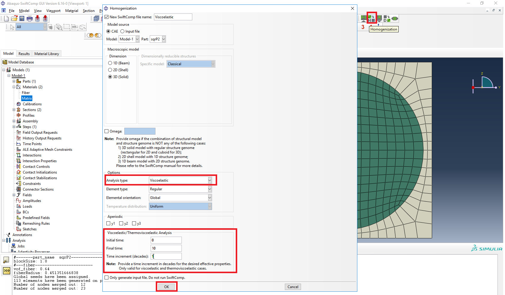 Definition of the viscoelastic homogenization step
# Step 6. We click on Ok to run the homogenization step. SwiftComp on the background will run the homogenization.
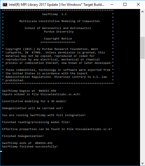 SwiftComp running on the background
# Step 7.The results can be found in the .sc.k file as shown next. Note that the effective properties will be outputted for each specified time.
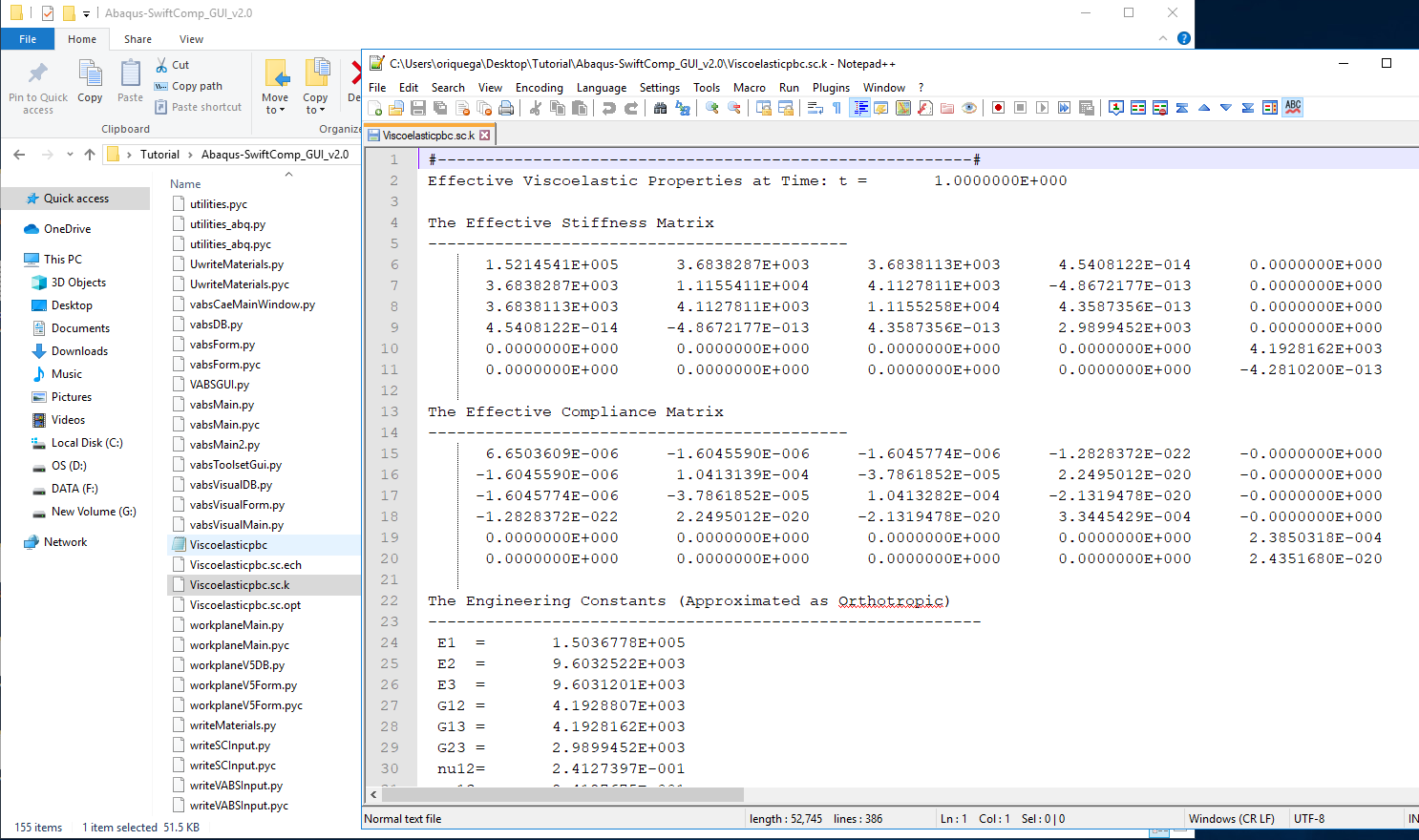 Results corresponding to the effective viscoelastic properties
# Step 8.We move on to macroscopic homogenization of the trac boom.
(Image(t1.PNG, desc="Trac boom") failed - File not found)
# Step 9.Go to Module > Property > Create Material and create a material with the properties obtained in the previous step.
(Image(t2.PNG, desc="Material properties") failed - File not found)
# Step 10.’We move on geometry and create the cross section from Module > Property > Create Section . Create a section, Layup-1, shown as below with Solid-Composite. Note here that the thickness of each layer should be actual thickness instead of relative thickness.
(Image(t3.PNG, desc="Layups") failed - File not found)
# Step 11.To create the geometry, in the SwiftComp Toolset, click the “Set sketch plane for 1D/2D customised SG” and secelt the 2D option. In the toolbox of the Part module, click ‘Create Shell: Planar’ , following the prompt, select the datum plane and the datum axis. Sketch the shape shown below. Click ‘Done’, then the part will be generated
(Image(t4.PNG, desc="sketch plane") failed - File not found)
(Image(t5.PNG, desc="Trac boom part sketch") failed - File not found)
(Image(t7.PNG, desc="Trac boom part") failed - File not found)
# Step 12.First we will assign the layup for the segment on the right. Make the two partition as shown and Click ‘Assign Layups’ in the SwiftComp toolset. Pick the area in the right, pick the appropriate baseline and select section ‘Layup-1’. Click ‘OK’. Repeat the step for all segments.
(Image(t8 .PNG, desc="Trac boom partitioning") failed - File not found)
(Image(t9.PNG, desc="Assigning layups") failed - File not found)
# Step 13.To assign local coordinates, go to Module > Property > Assign Material Orientation Following the prompt, we first select the top segement to be assigned a local material
orientation, and click ‘Done’. Then in the prompt area, click ‘Use Default Orientation or Other Method’ button. In the ‘Edit Material Orientation’ dialog box, select ‘Discrete’ as the Orientation
Definition. Then click , open the ‘Edit Discrete Orientation’ dialog box. In the Normal axis definition choose Vector (i,j,k), and set the vector (1.0, 0.0, 0.0). For Primary Axis, choose 1 as the Primary axis direction and Edges as the Primary axis definition. Click to select the light blue edge shown in the figure below, then click ‘Done’. Use Flip Direction to make the axis pointing to the right if necessary. Click ‘Continue…’ then ‘OK’ to finish this assignment. Same procedure for the rest three segments. Some steps may not be exactly the same. The only requirement is to make sure that the asix 2 pointing outwards.
(Image(t12.PNG, desc="material orientation") failed - File not found)
(Image(t11.PNG, desc="material orientation") failed - File not found)
# Step 14. Module > Mesh > Seed Part ad choose mesh size, then lick Click ‘Mesh Part’
(Image(t13.PNG, desc="Mesh") failed - File not found)
# Step 15. Homogenize the par to get the final results.
(Image(t14.PNG, desc="Homogenization") failed - File not found)
References
- Liu, X.; Tang, T.; Yu, W., Pipes, R. B.: “Multiscale modeling of viscoelastic behavior of textile composites,” International Journal of Engineering Science, Vol 130, September 2018, pp. 175-186, DOI: 10.1016/j.ijengsci.2018.06.003.
- Rique, O.; Liu, X.; Yu, W., Pipes, R. B.: “Constitutive modeling for time- and temperature-dependent behavior of composites,” Composites Part B: Engineering, Vol 184, March 2020, DOI: 10.1016/j.compositesb.2019.107726.