Elastic Generalized Free Edge analysis of a Sandwich Plate with Stiffener having an uniform cross-section
In this example, we want to compute the elastic effective properties of a Hat Stiffener Sandwich Plate with uniform cross-section, fabricated from plain weave lamina. The Hat Stiffener consists of a single layer woven lamina wrapped around a polyurethane foam and the stiffener gets its name from its hat shaped cross section. The material properties of the woven lamina and the foam is provided in the table below.
 Material Properties
This Tutorial focuses on-
The types of material assignment.
The types of material orientation assignment.
The types of meshing to perform generalized free edge stress analysis.
Software Used
We will use SwiftComp 2.1 and Abaqus CAE with the Abaqus SwiftComp GUI for this tutorial. Abaqus CAE will be used to model the sandwich plate and to run the homogenization while SwiftComp runs in the background.
Solution Procedure
Below describes the step-by-step procedure followed to solve the problem.
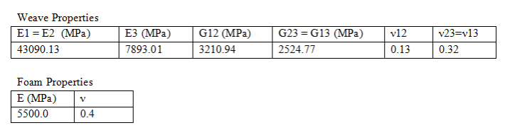
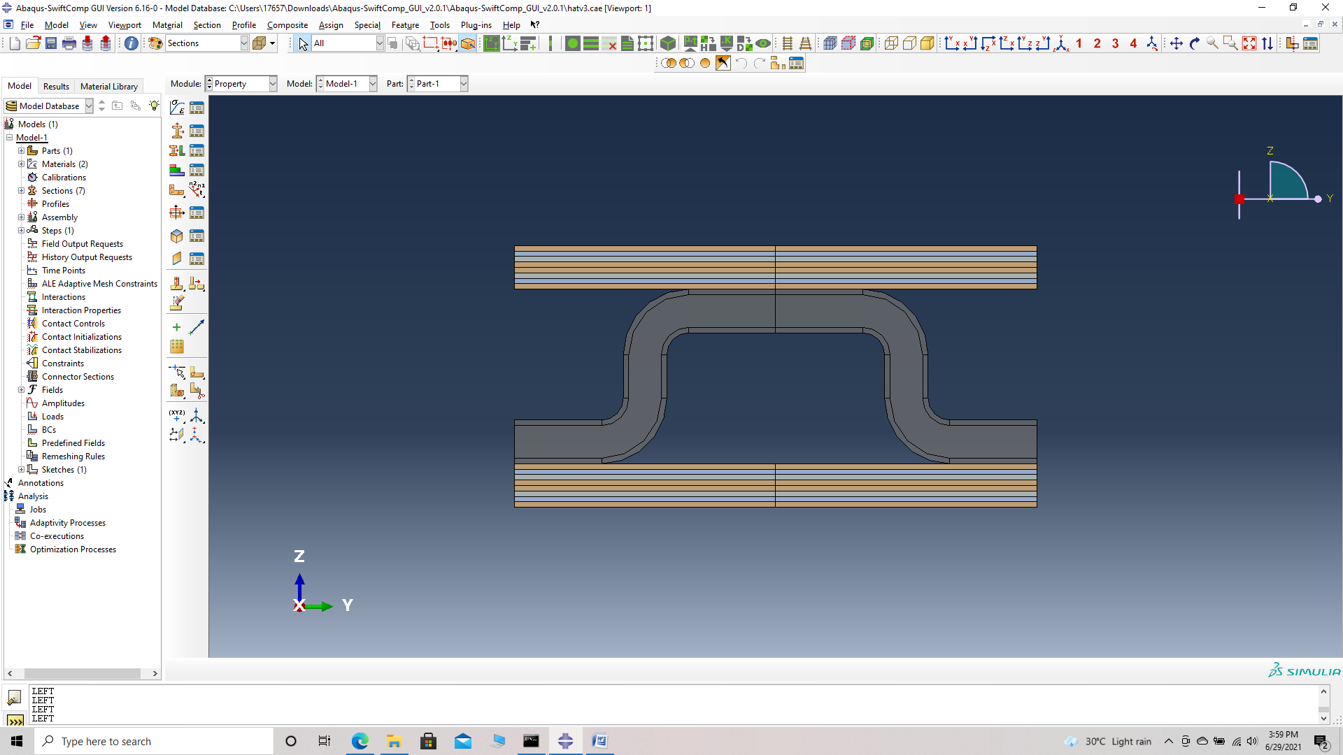
# Step 1. Set sketch plane for customized SG -> choose 2D SG -> Create planar shell -> Select the plane and vertical axis -> Sketch the cross section shown. Remove the appropriate faces using the remove faces tool to obtain the cross-section shown
 Cross-section Sketch
 Cross-section
# Step 2. Enter the material properties for the model. Within the Materials section of Abaqus CAE, we create a isotropic material called ‘Foam’ and add the corresponding foam properties. Similarly we add the engineering constants of the weave.
 Foam material properties
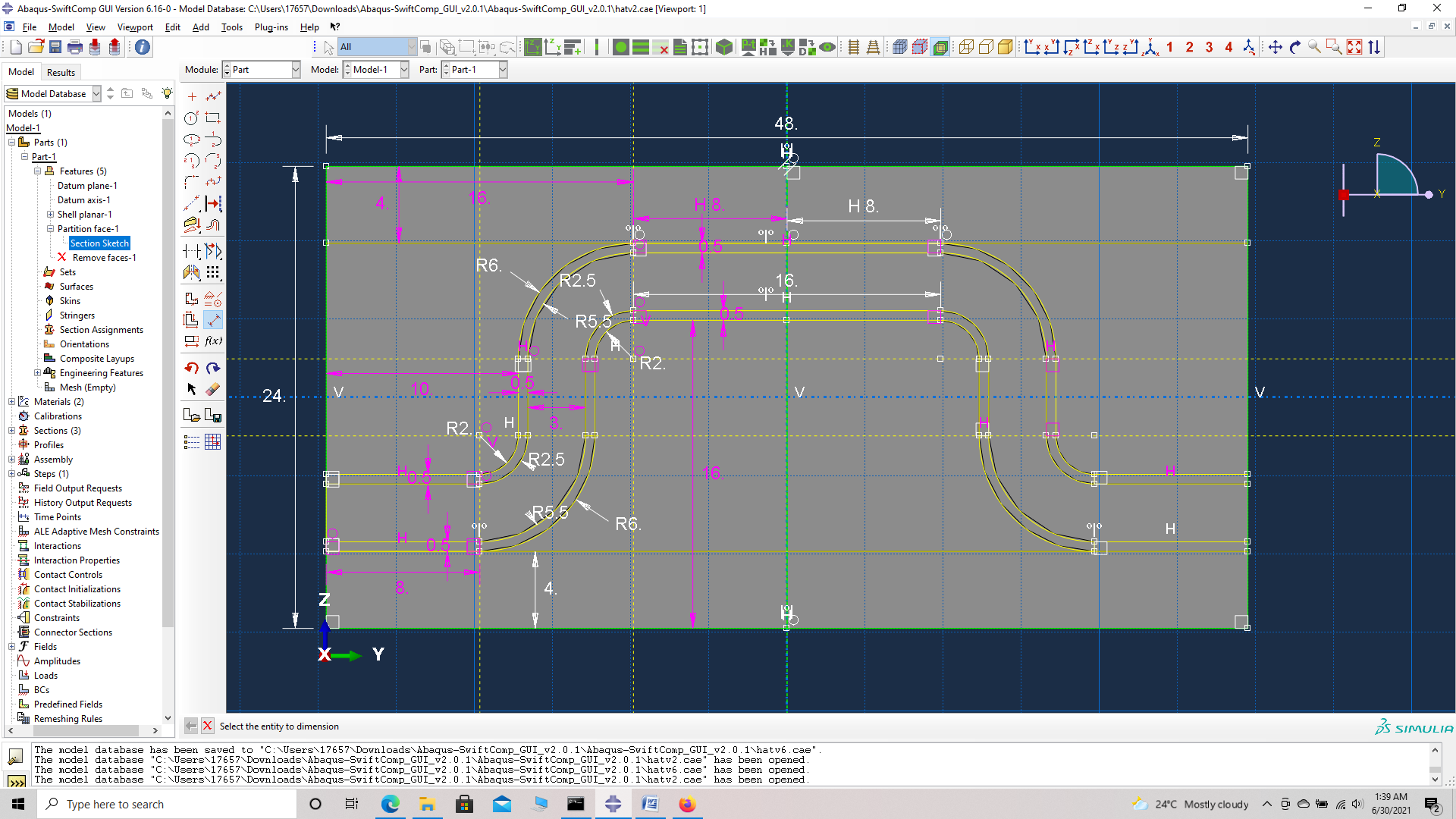
# Step 3. Create a Section ‘Section -1’ using the Create Section option, select the material as foam and add the shell thickness as 0.1 ( shell thickness does not affect the results, and is usually kept between 0.1 -1 ).
 Creating Foam section
# Step 4. Now go to New Layups and choose the material as weave , add the section name as Weave Section, Define the Layup as (0/45/-45/0)s and set the thickness to 0.5 mm and create the required layup. The sandwich laminates are 4 mm thick, and the plies are 0.5 mm thick. So we will have 8 plies per laminate.
Layup = (0/45/-45/0)s
 Layup
Layup
We describe three methods of Material Assignment as follows:
Material Assignment method 1 – Layup assignment
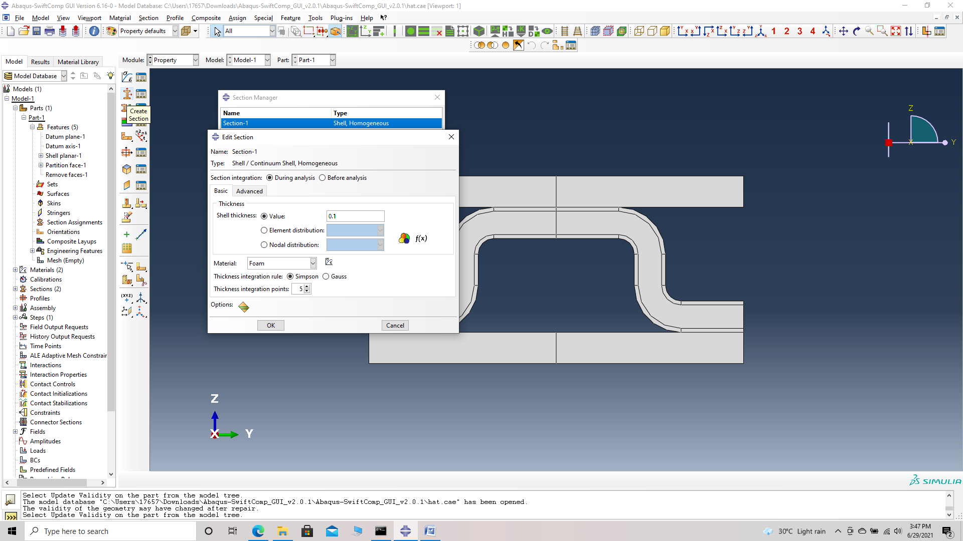
# Step 5. To assign the layup, go to Create 2D SG: Assign Layups and the pick the area, the baseline and the line opposite to the baseline for all the sandwich laminates as shown and then hit Ok.
 Pick laminate area
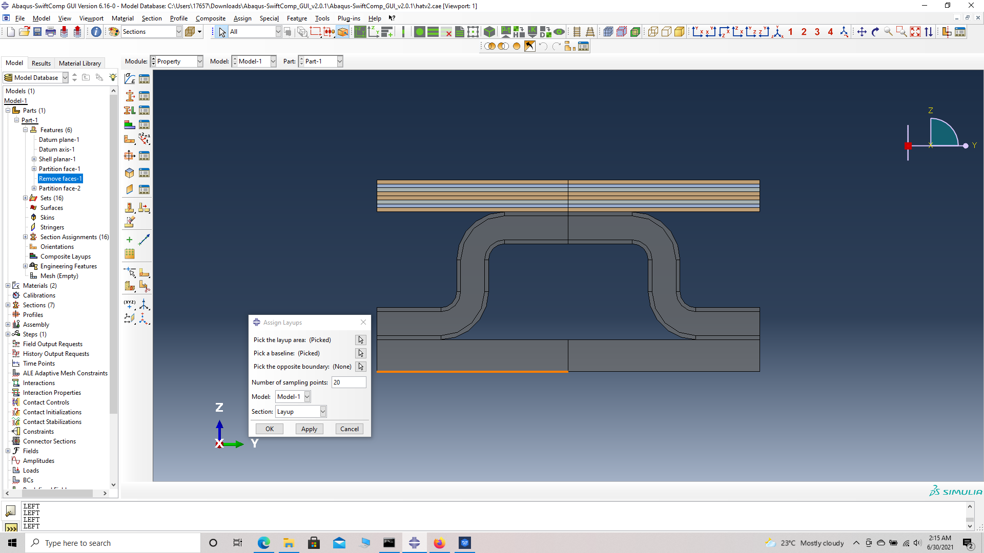 Pick laminate baseline
 Pick the line opposite to the baseline
 laminate
Material Assignment method 2 – Layup assignment with manual partition
# Step 6. To assign the material for the cover ply of the stiffener, go to Assign section and the pick the cover ply choose done and pick the weave_0.0 section which is automatically generated when we assigned the layup with orientation as (0/45/-45/0)s. We will also have
weave_45.0 section and weave_-45.0 section.
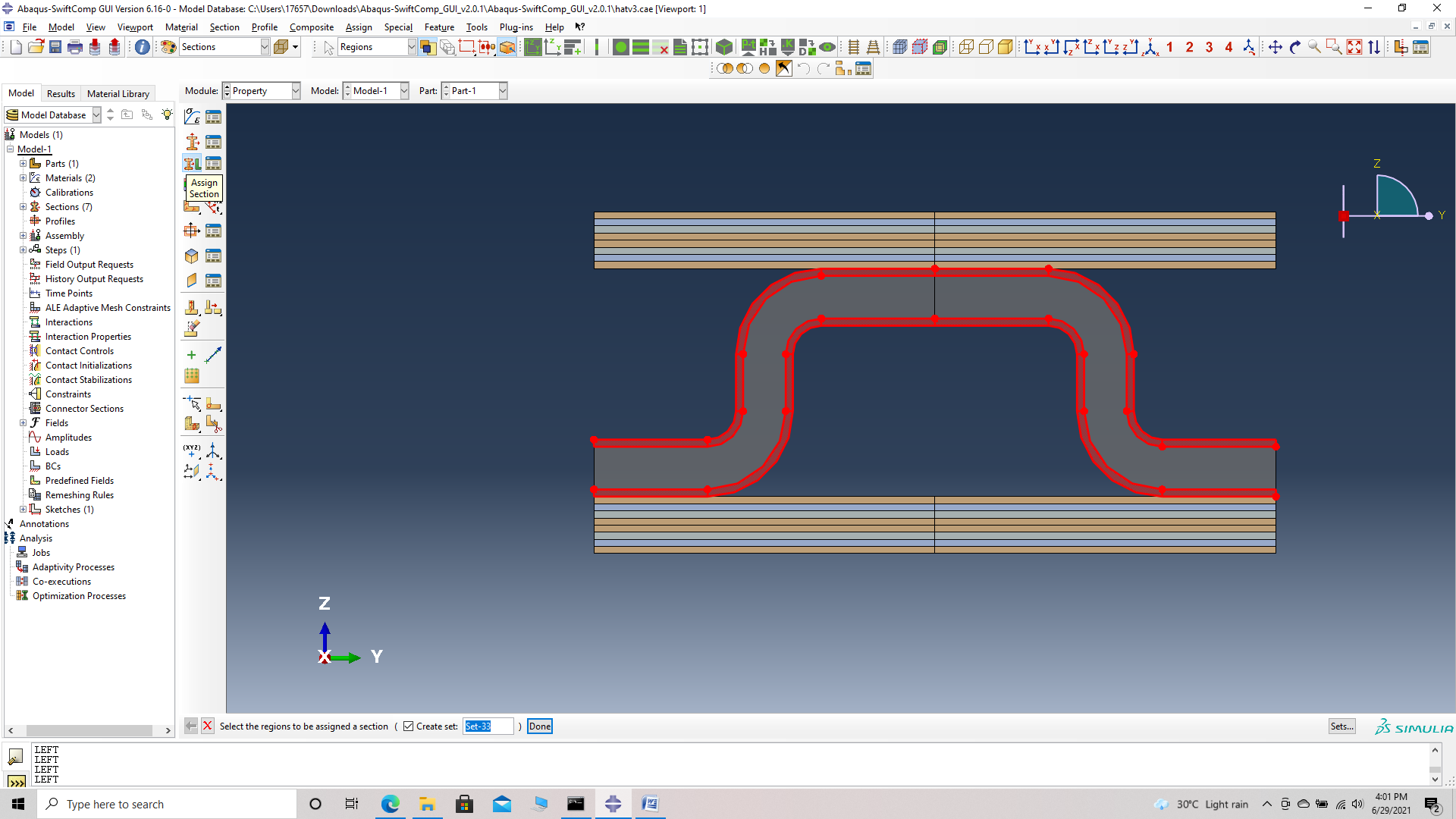 Pick cover ply area
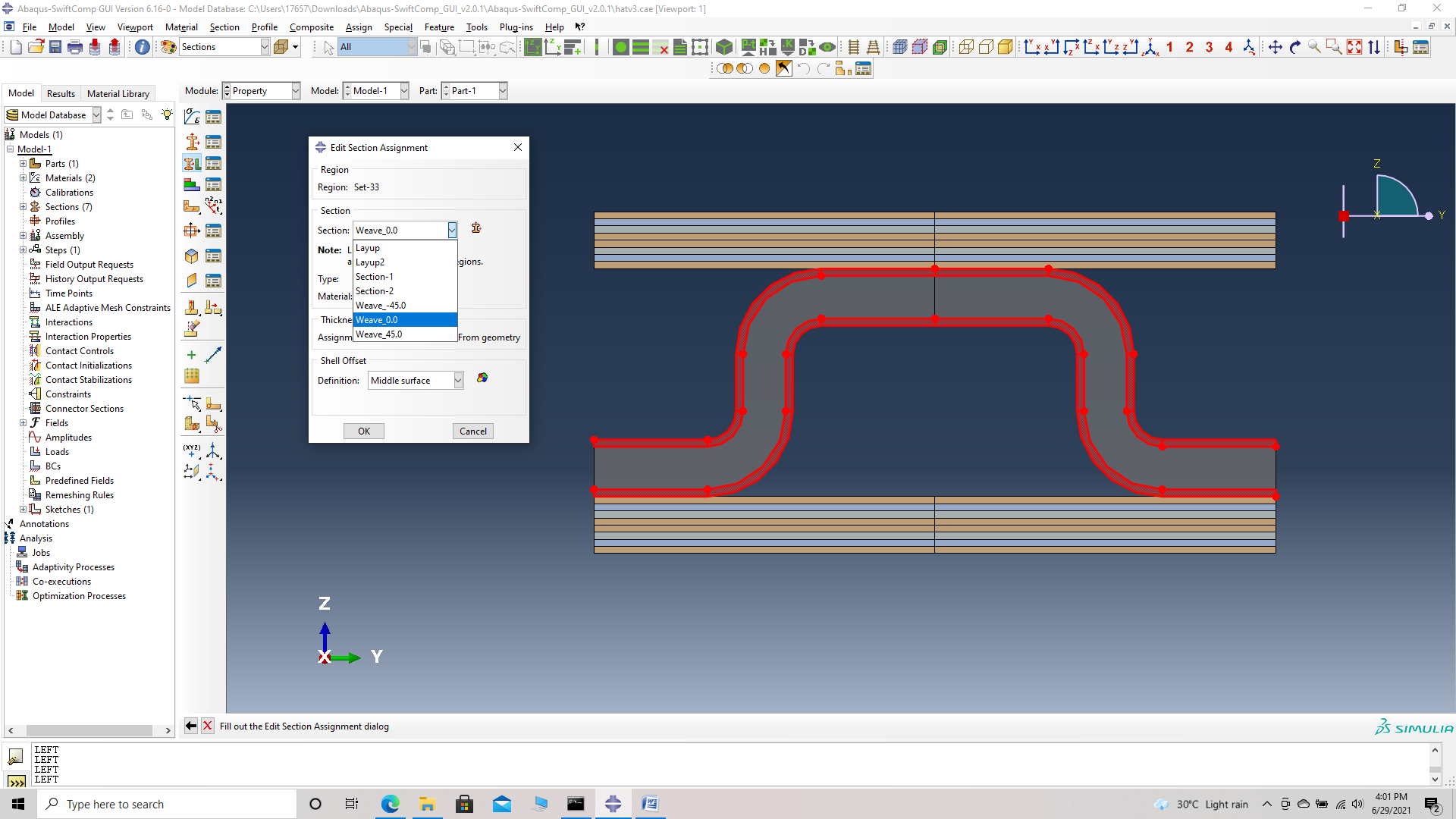 Pick Weave_0.0 section
Material Assignment method 3 – Standard Abaqus section assignment with manual partition
# Step 7. To assign the material for thefoam of the stiffener, go to Assign section and the pick the foam, choose done and pick the section ‘Section-1’ created in step 3.
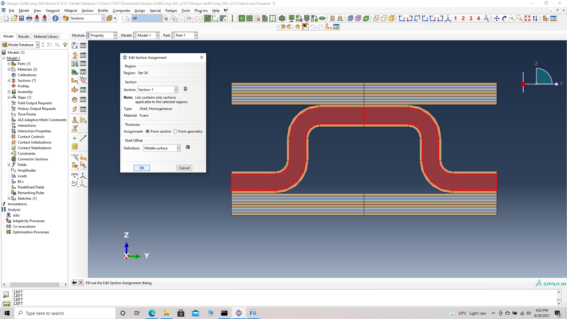 Pick foam section
Now we assign the material orientation for the part. Orientation Axis 1 represents the y2 axis of SwiftComp’s local orientation and orientation axis 2 represents y3 axis of SwiftComp’s local orientation.
We describe four methods of Material orientation Assignment as follows:
Material Orientation Assignment method 1 -Definition -> Global
‘ # Step 8. Go to Assign material orientation -> select the sections of the weave with the same orientation as the global axes -> Done -> Select a CSYS (use default orientation or other method) -> Definition (Global) -> Define -> OK.
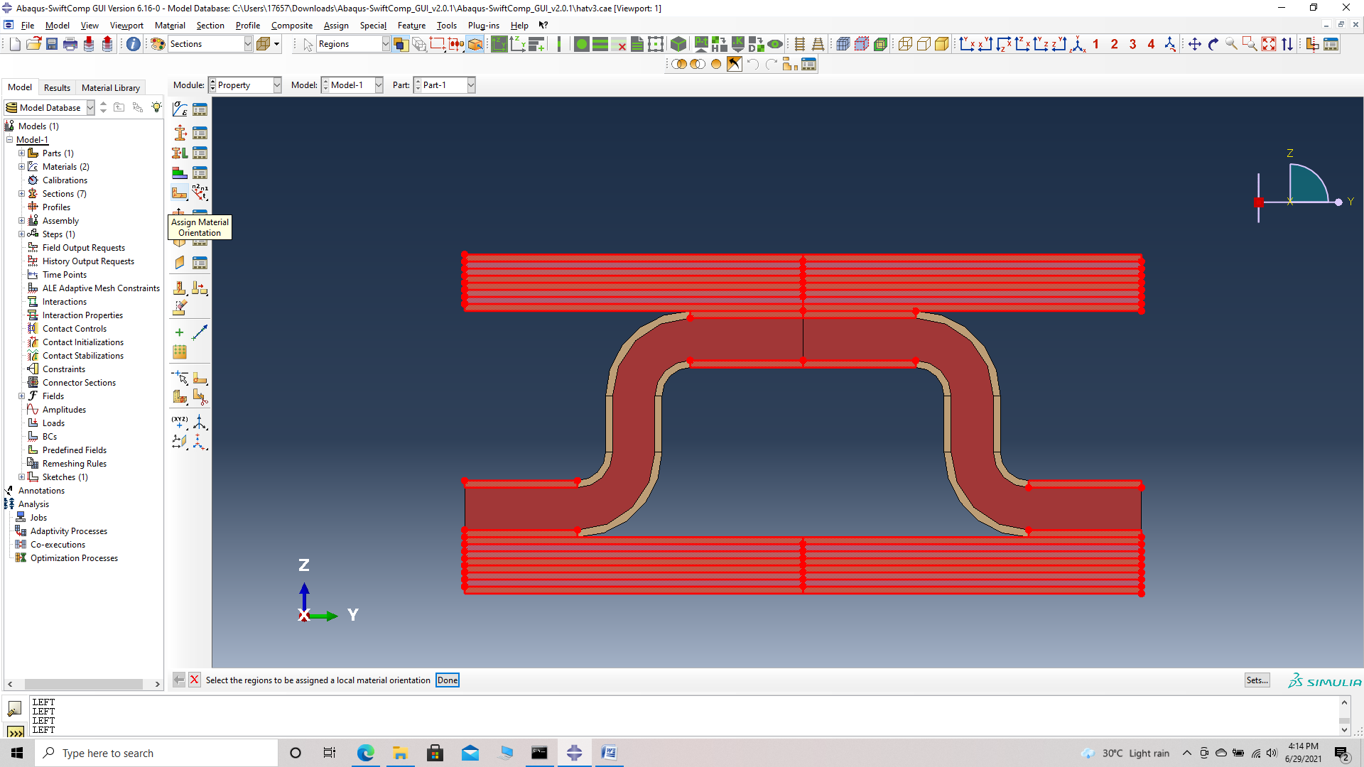 Assign material orientation
 Selecting a CSYS - use default orientation or other method
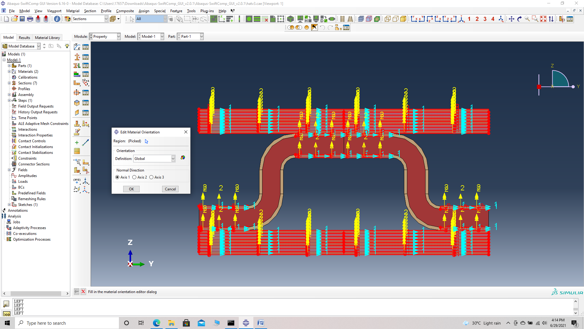 Global material orientation
Material Orientation Assignment method 2 -Definition -> Discrete
‘ # Step 9. Go to Assign material orientation -> select the two sections of the part shown which have the same orientation -> Done -> Select a CSYS (use default orientation or other method) -> Definition (Discrete) -> Define -> Primary axis orientation -> choose edge and flip direction if needed to make the axis point along the layup -> Choose the surfaces for the normal axis definition -> Continue -> OK.
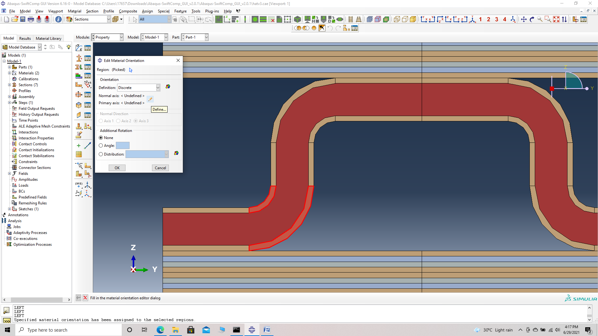 Discrete material orientation
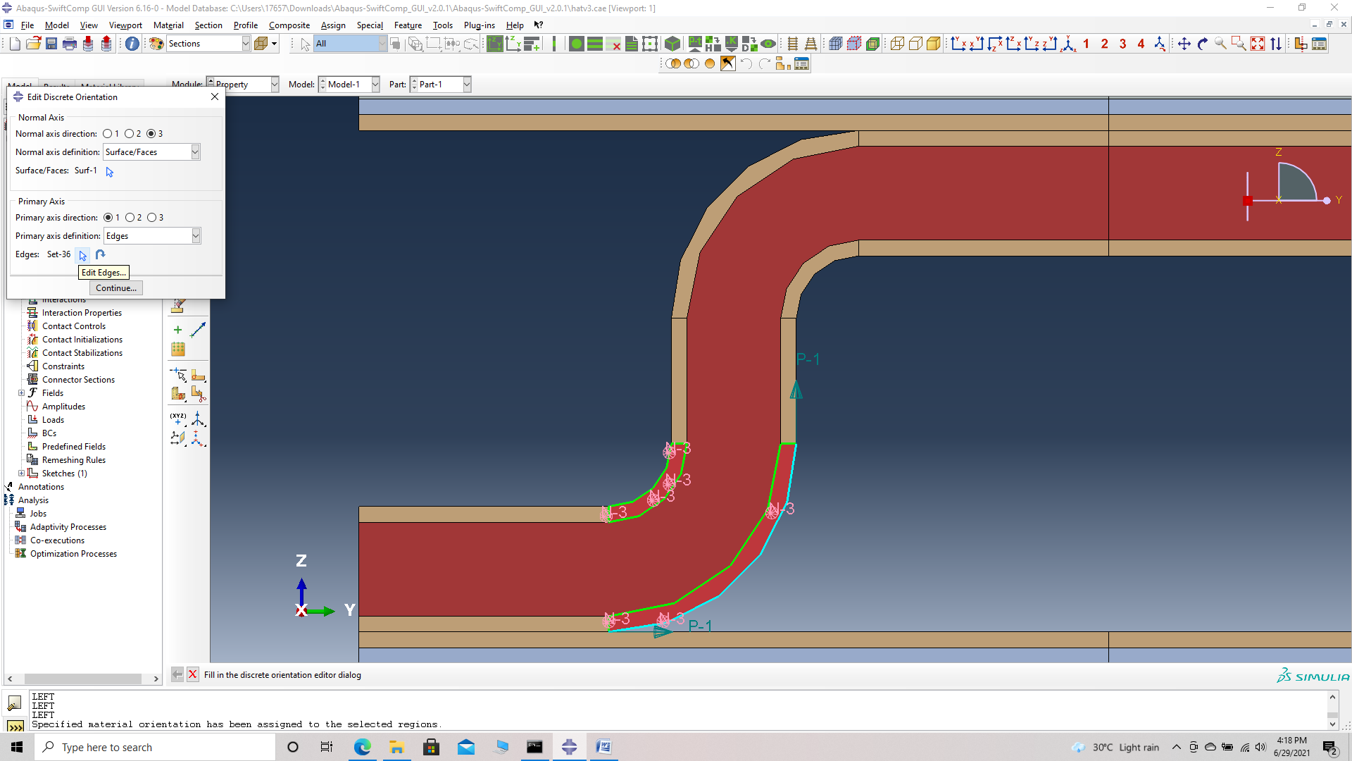 Defining the axis
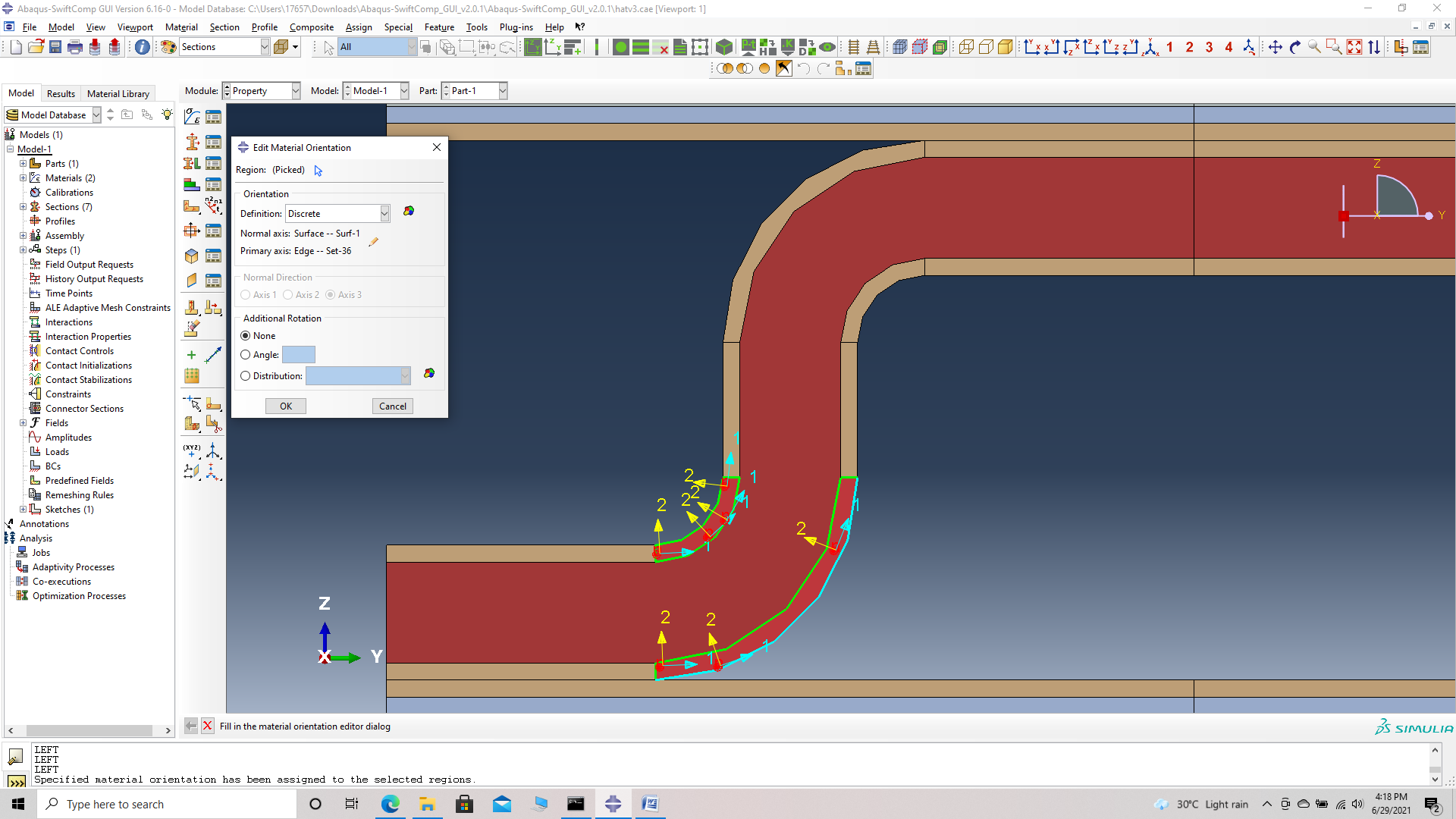 Discrete material orientation
Material Orientation Assignment method 3 -Definition -> Global with different normal axis
‘ # Step 10. Go to Assign material orientation -> select the sections of the weave shown with its orientation perpendicular to the global axes -> Done -> Select a CSYS (use default orientation or other method) -> Definition (Global) -> Normal direction -> Axis 2 (axis points along the layup) -> OK.
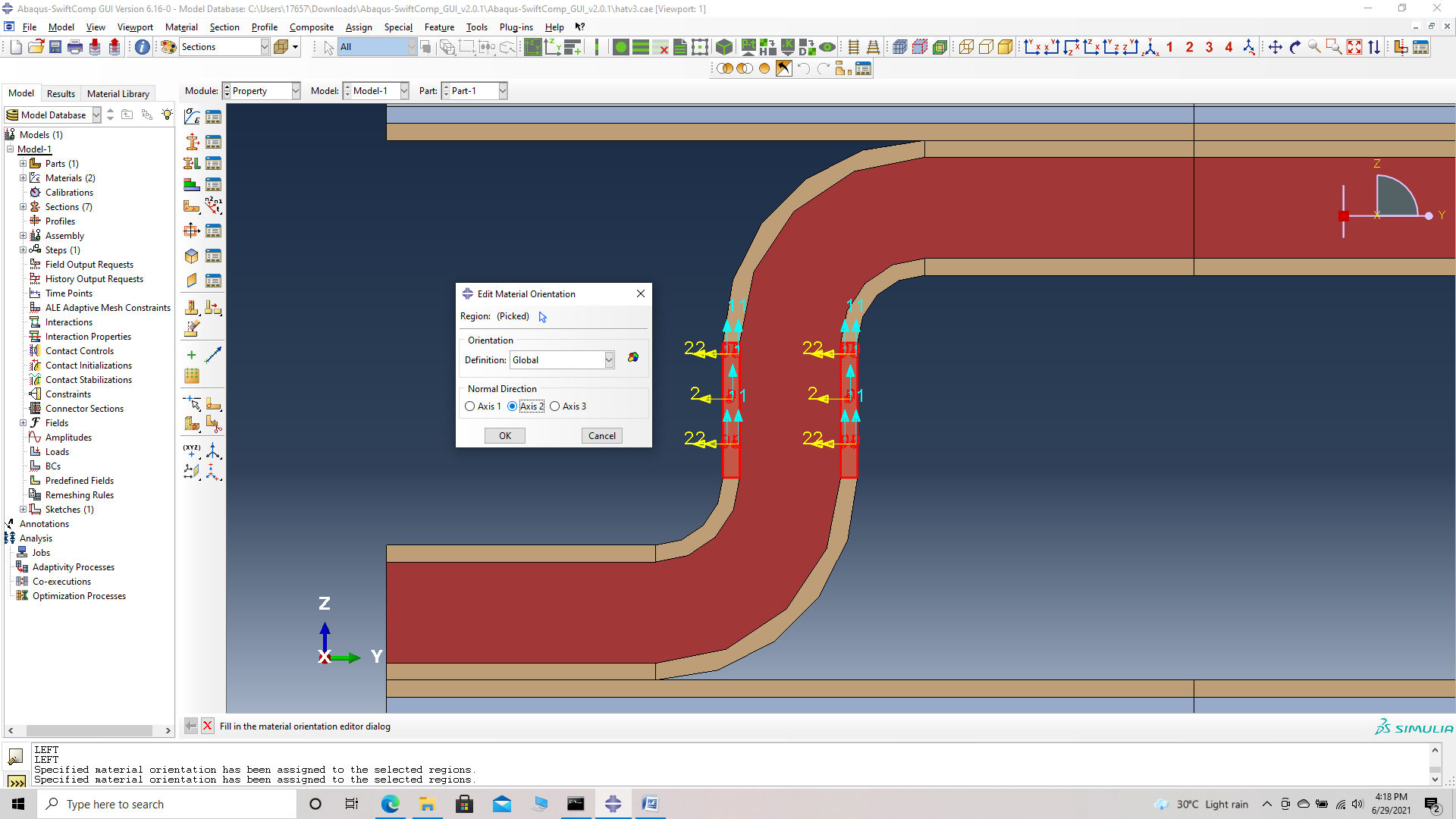 Global material orientation with different normal axis
Material Orientation Assignment method 4 -Definition -> Coordinate system with different normal axis and rotation
‘ # Step 11. Go to Assign material orientation -> select the sections of the weave shown with its orientation perpendicular to the global axes -> Done -> Select a CSYS (use default orientation or other method) -> Definition (Coordinate system) -> Normal direction -> Axis 2 -> Rotation -> 180 -> (axis points along the layup) -> OK.
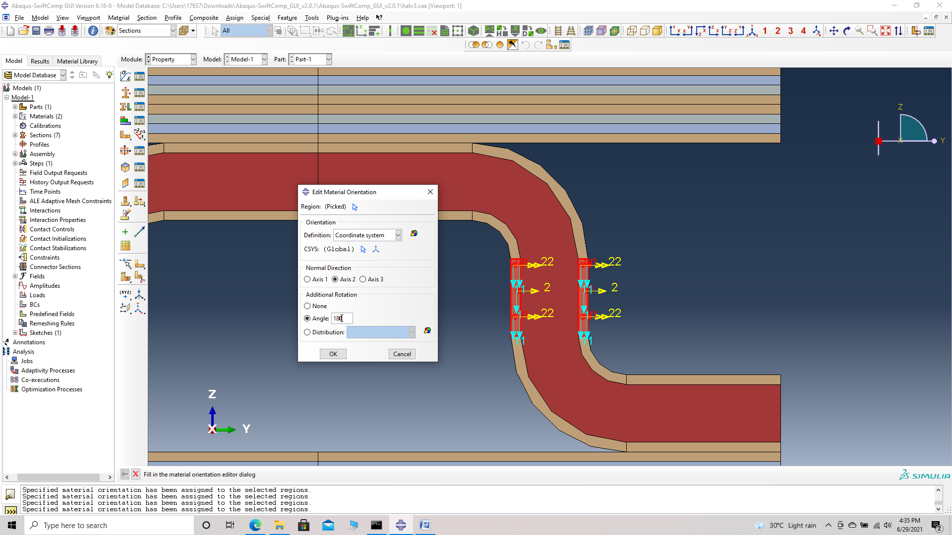 Coordinate system with different normal axis and rotation
‘ # Step 12. Use the second method of Material Orientation Assignment (Discrete) for all the other curve to get the oriented part as shown.
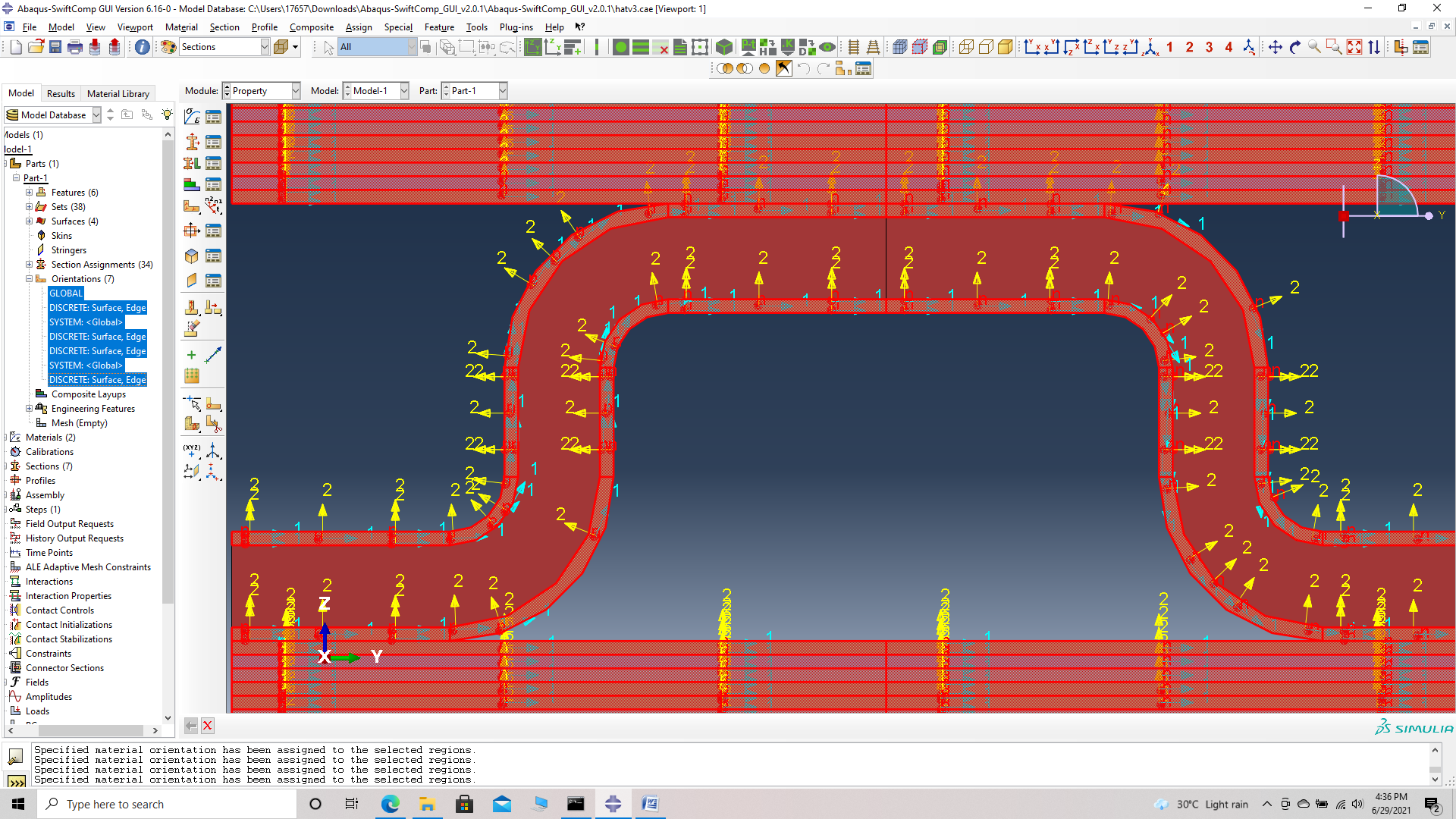 Final part material orientation
‘ # Step 13. Now go to Assemble, create the part instance with dependent mesh.
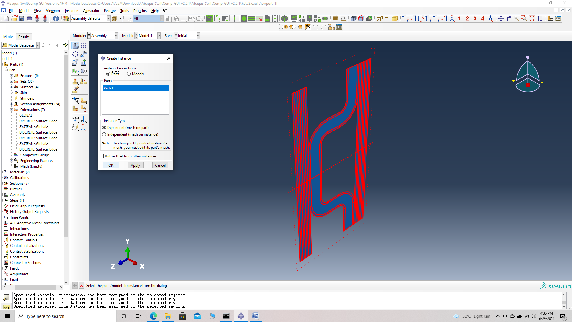 assembly
‘ # Step 14. In the Mesh section, partition the part as shown to get even mesh.
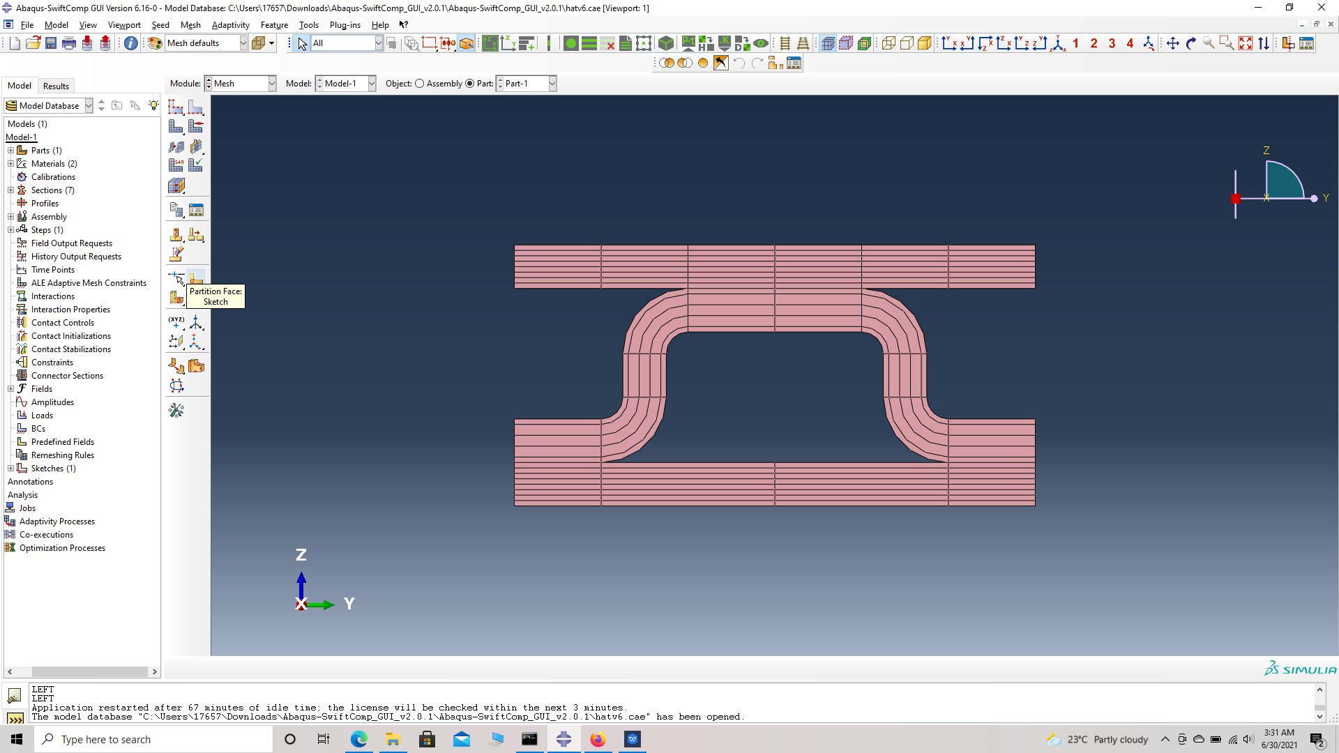 Partition
Now we mesh the part for our Generalized Free Edge Analysis.
We describe three methods of Meshing as follows:
Mesh technique 1- Seed edge, by number, with double bias.
‘ # Step 15. Go to Seed edge -> select the vertical edges of plies as shown in figure. Select mesh by number with 10 elements and choose double bias. This will provide finer mesh for the inter-ply regions and a coarser mesh in the middle of each ply.
 Seed edges
 Seed edge by number with double
Mesh technique 2- Seed edge, by size, with single bias.
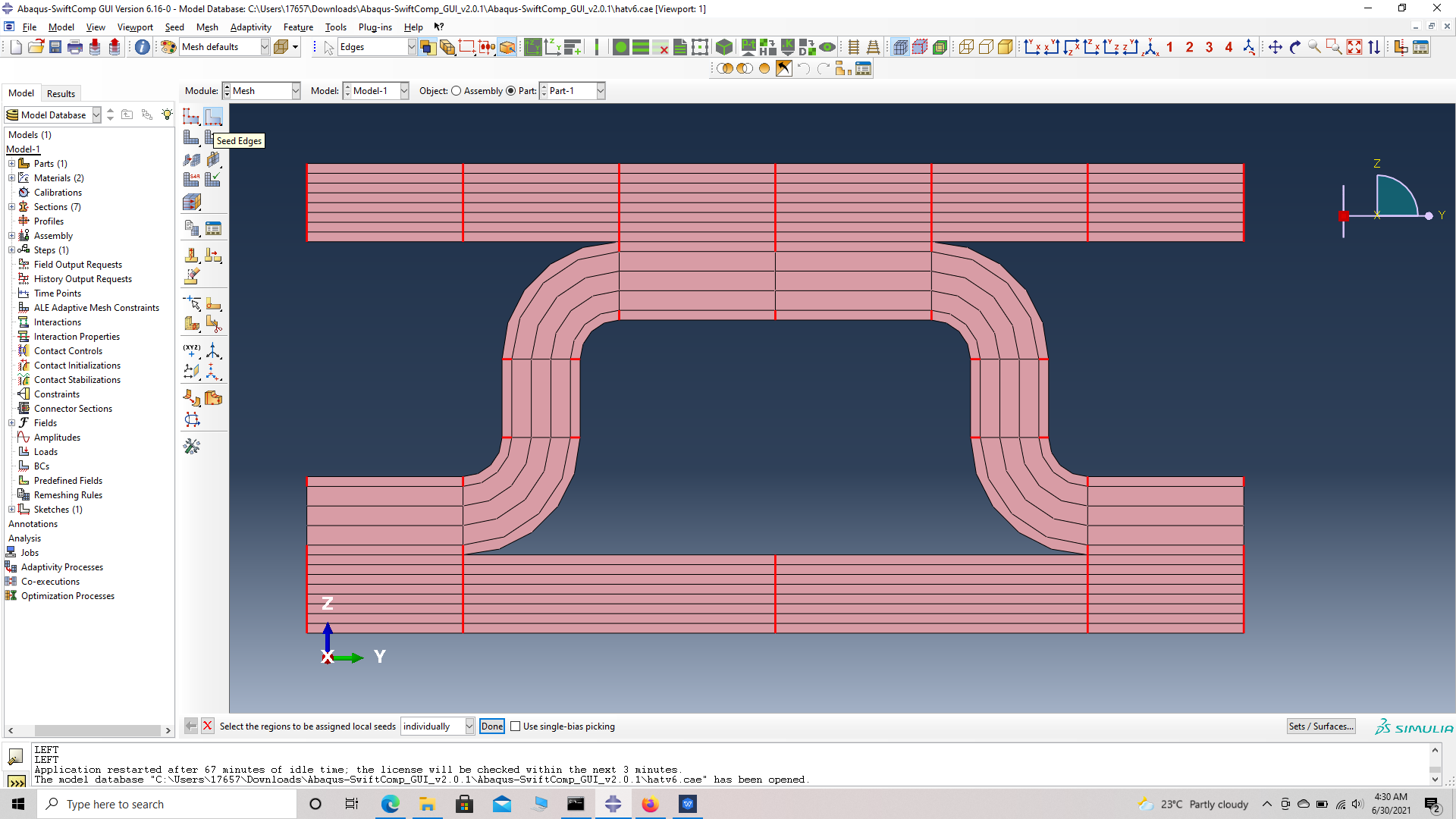
‘ # Step 16. Go to Seed edge -> select the horizontal edges of part as shown in figure. Select mesh by size ranging from 0.05 to 0.25 and choose single bias. Flip the direction if necessary to make the direction point outward. This will provide finer mesh for the end of ply regions and a coarser mesh in the middle of each ply.
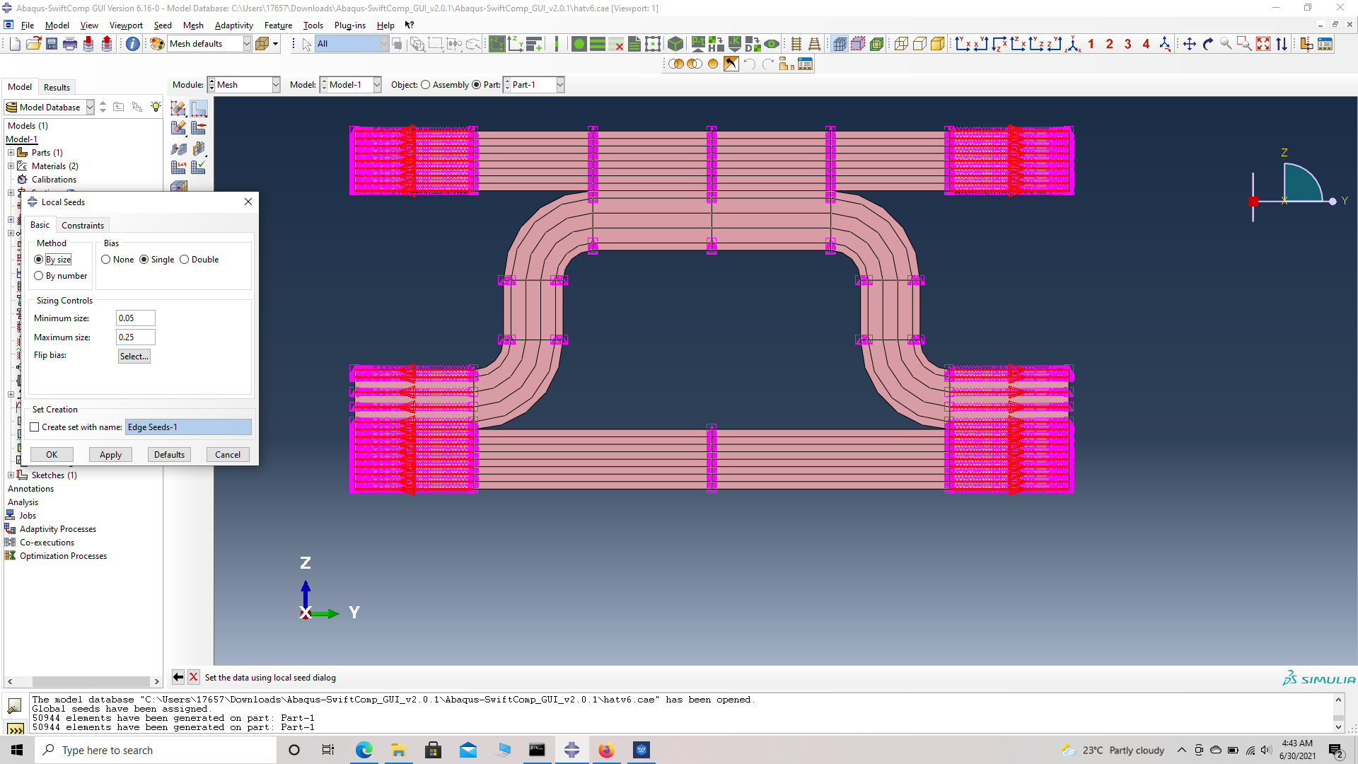 Seed edges
Mesh technique 3- Seed part, by size, with no bias.
‘ # Step 17. Go to seed part -> select mesh sizeas 0.25 and choose no bias. as shown in figure. This will provide uniform mesh for thepart unless superimposed by seed edge.
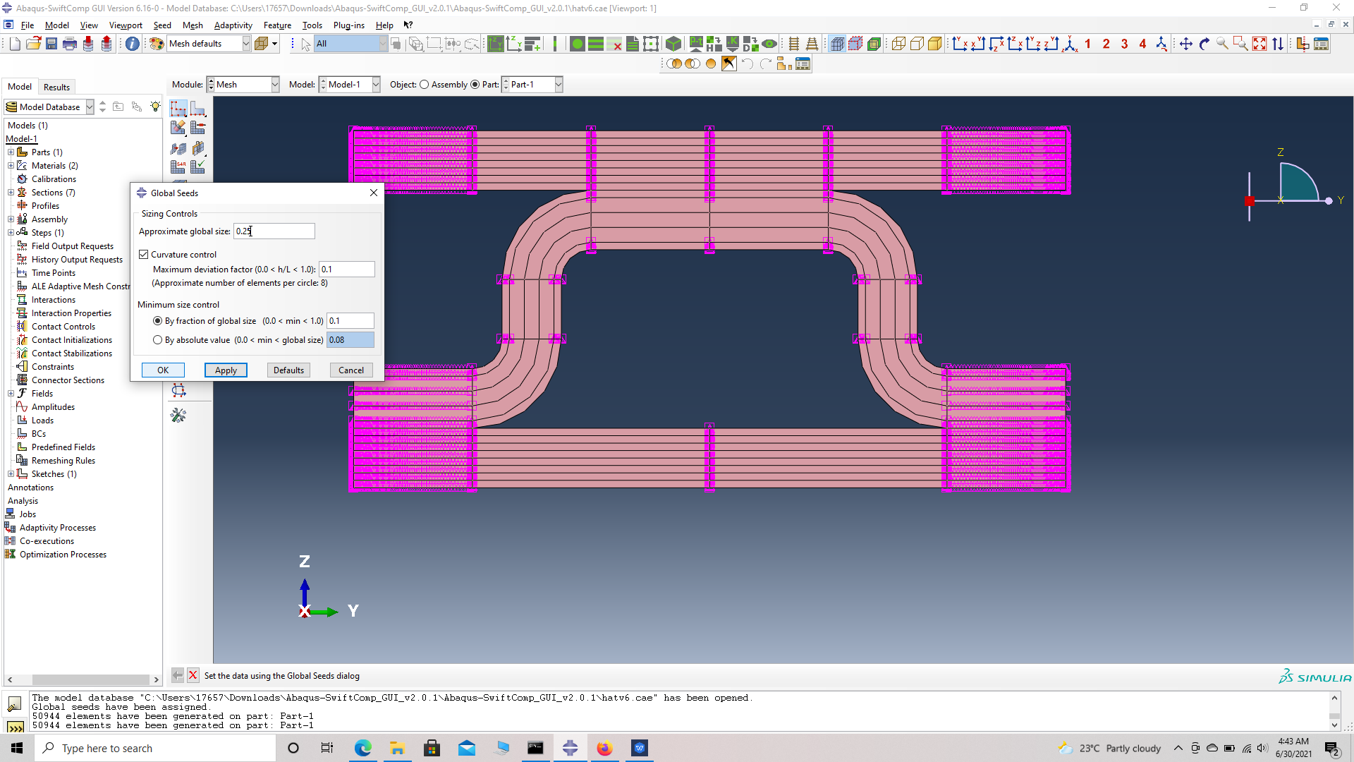 Seed part
‘ # Step 18. Click ‘Mesh Part’.
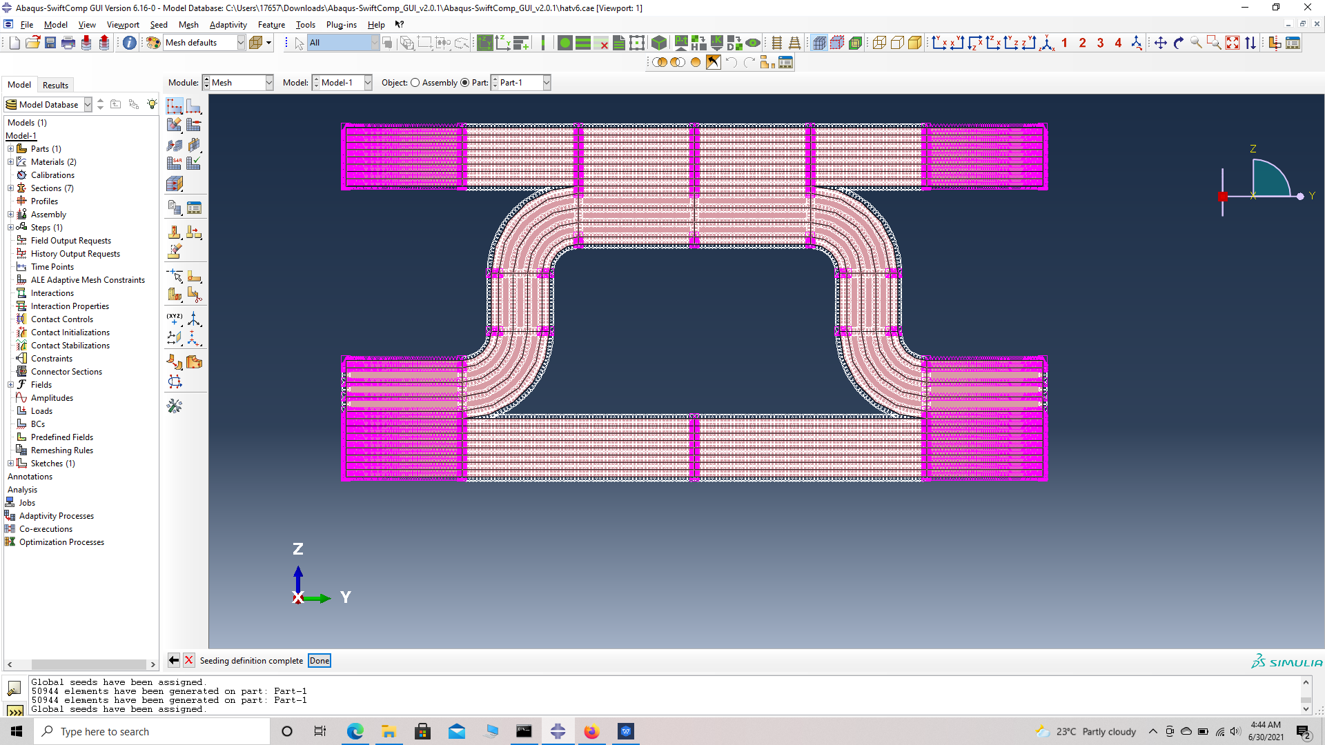 Seeded part
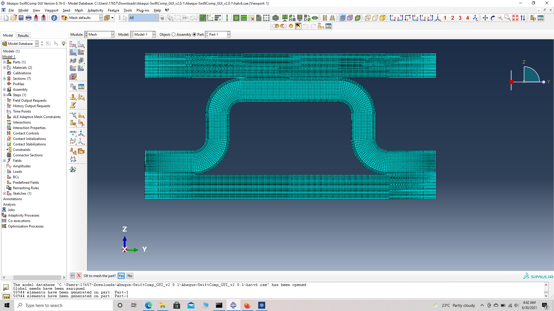 meshed part
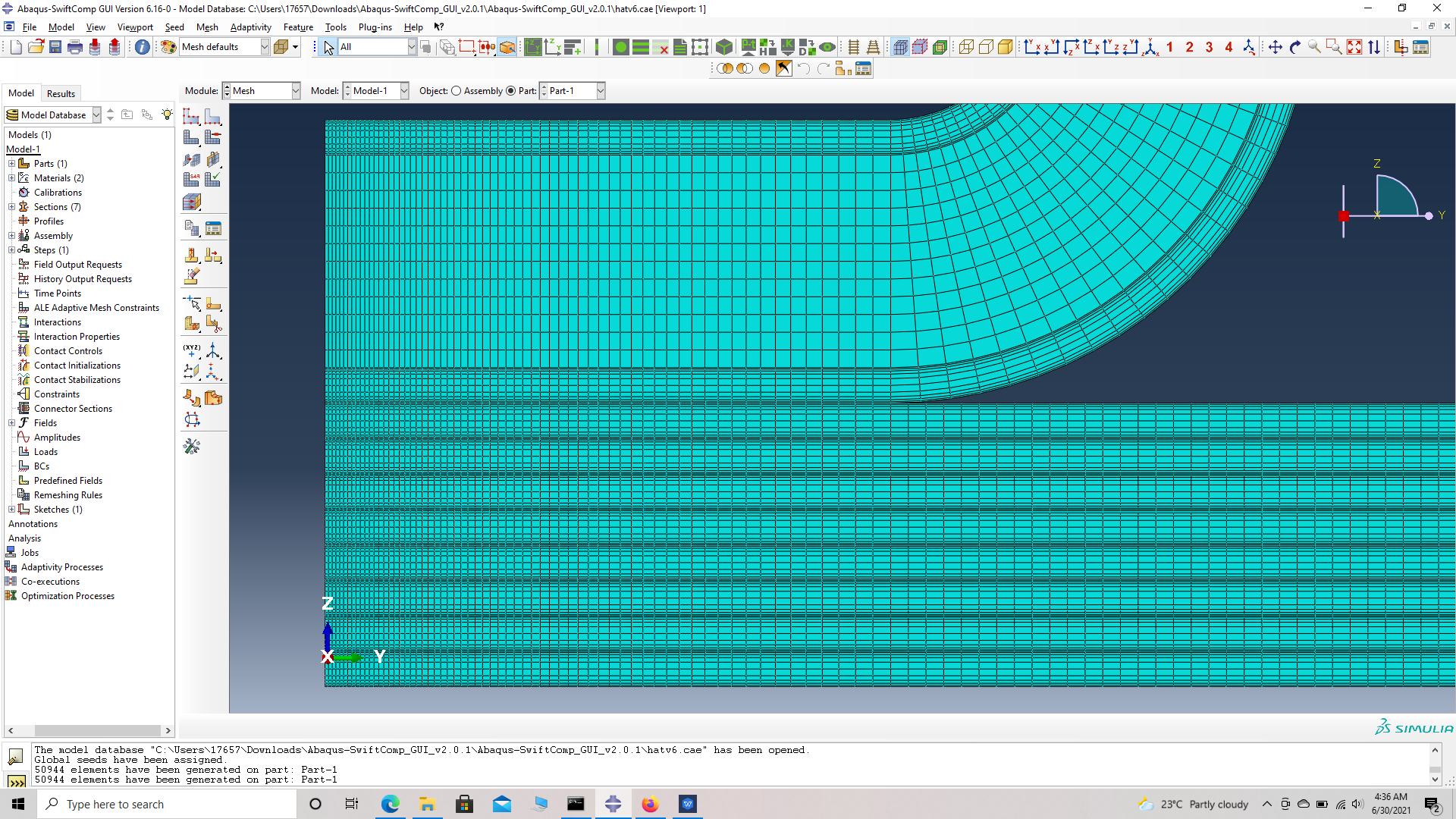 closer view of mesh
# Step 19.Create a job and write its input file.
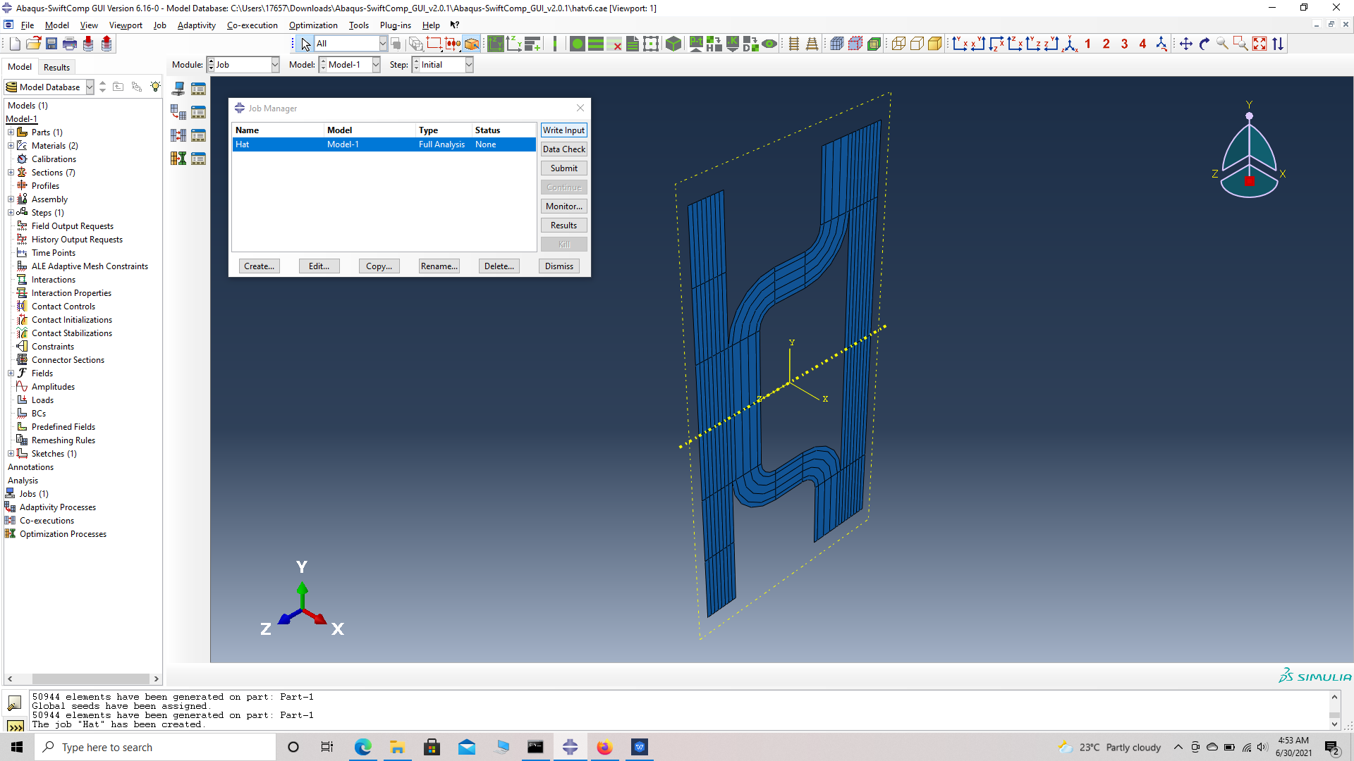 ip file
# Step 20.To the effective elastic properties. we click on Homogenization and select elastic in Analysis Type. Homogenize the part as a 3D Solid using the Homogenization via input file option to get the final results.
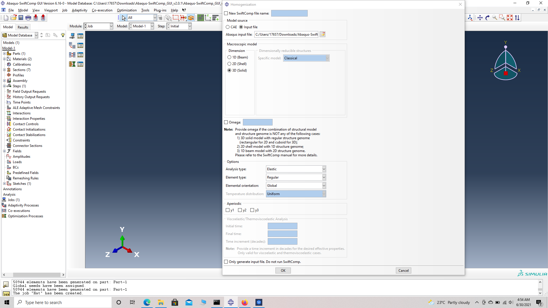 Homogenization
References
 # ref 1
 # ref 2