Elastic analysis of a nacelle modeled using Abaqus and its constituent composite plate homogenized using Gmsh4SC
This tutorial shows how to calculate cross-sectional properties of a composite plate with elastic matrix and unidirectional transversely isotropic elastic fibers for given orientation and material properties using Gmsh4SC. This properties are used to model a nacelle of a wind-turbine in Abaqus, as a homogeneous solid body. Hence the nacelle component can be subjected to structural analysis, with reduced computational effort.
The orientation ie layup of the plates are (0/30/45/90/0/0/90/-45/-30/0) and the materials used are M30S fibers and PMT-F7 epoxy resin with the material properties given below.
The material properties of the PMT-F7 epoxy are, E = 2990 MPa and ν = 0.36.
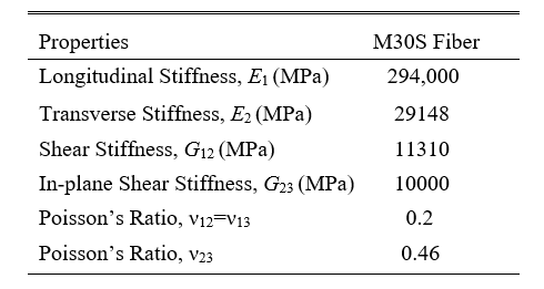 Fiber properties of M30S
Solution
The linear elastic MSG-based modeling of plate is solved in three steps.
1) Elastic homogenization of fiber and matrix at microscale, using Gmsh4SC.
2) Elastic homogenization of the layup (stack of oriented plates), using Gmsh4SC.
3) Modeling of the Nacelle component in Abaqus as a homogeneous body.
1)Elastic homogenization of fiber and matrix at microscale, using Gmsh4SC.
Gmsh4SC is available at cdmHUB.org. Go to https://cdmhub.org/tools/scstandard and launch the Gmsh4SC tool.
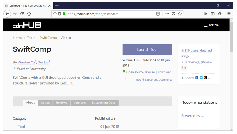 Gmsh4SC
1.1 Creating a new model
Go to File select New and save the model as shown in the figures below.
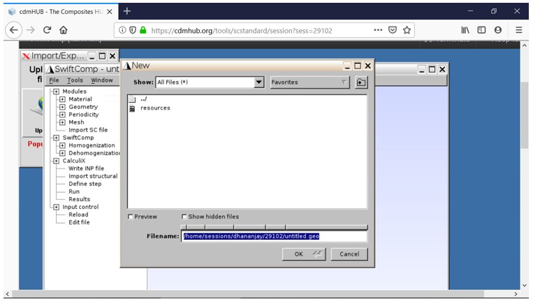 Saving the new model
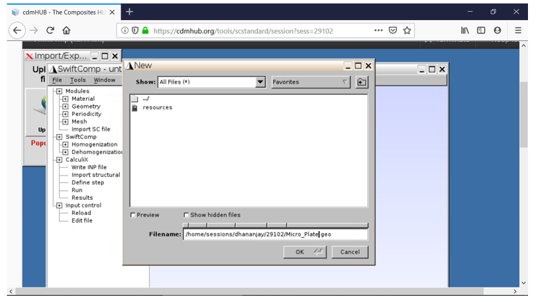 Saving the new model
1.2 Assigning the material properties:
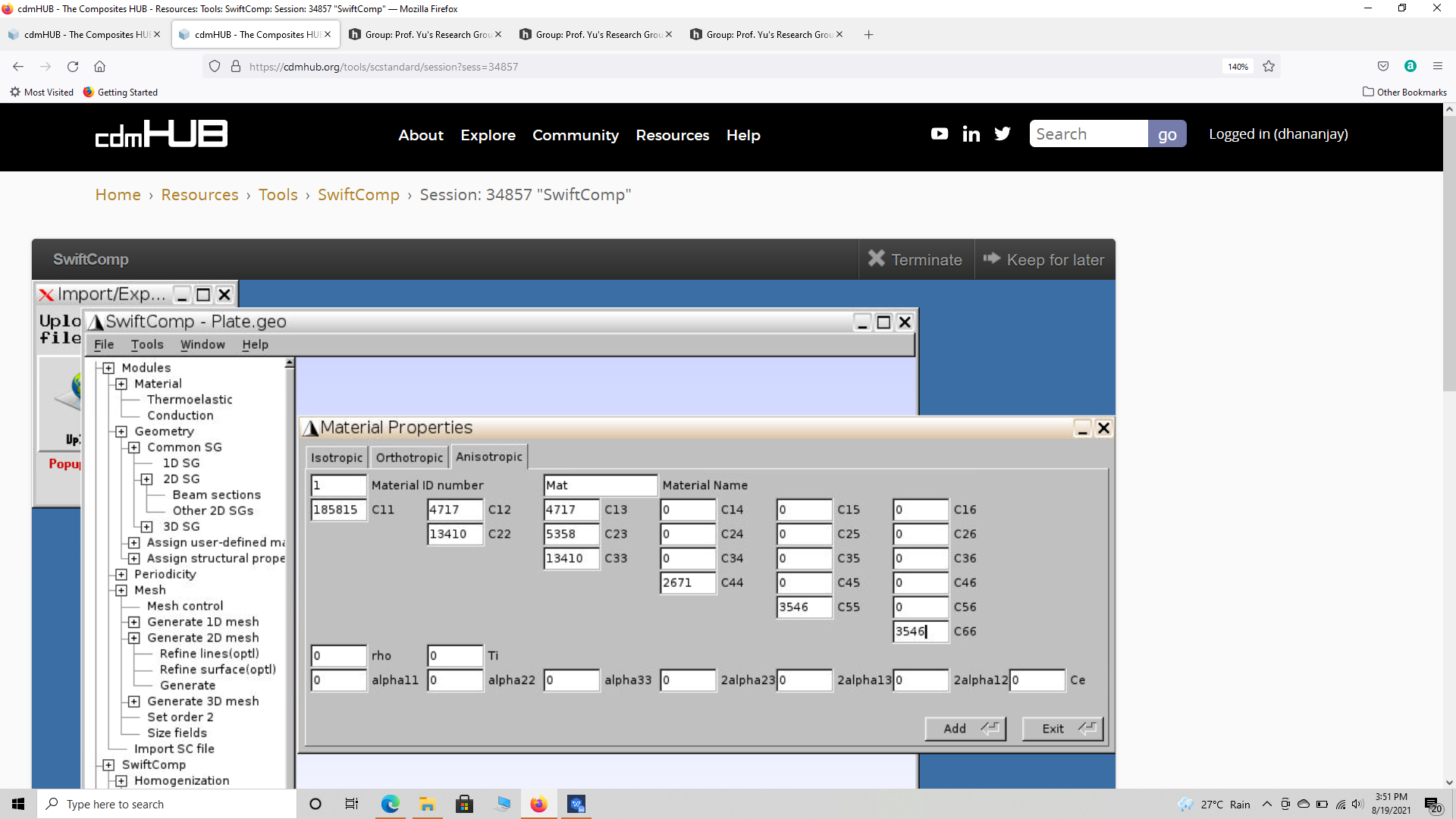
Go to Material select Thermoelastic and in the pop up window choose the material type (Isotropic, Orthotropic or Anisotropic) and set the material constants and material name, then select Add. Repeat this for all the materials required for the model and close the material properties window. For this tutorial we add the isotropic matrix and transversely isotropic elastic fiber properties under appropriate names.
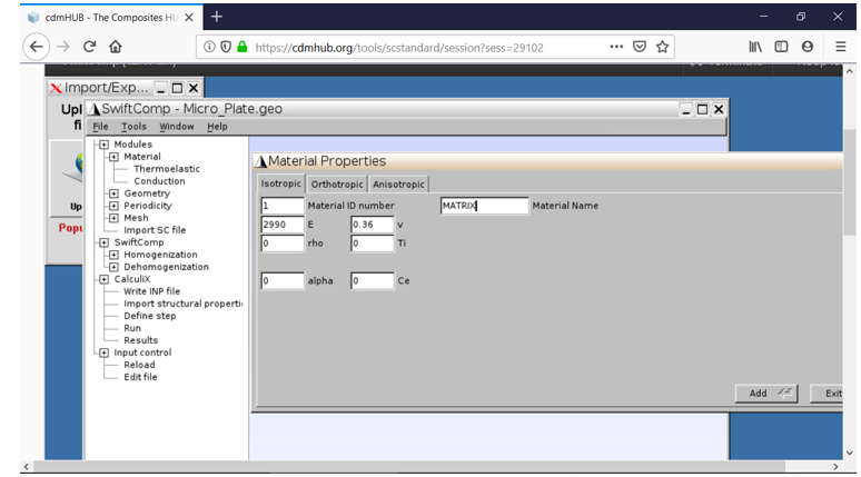 Assigning matrix material properties
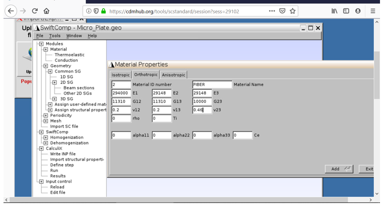 Assigning fiber material properties
1.3 Creating geometry
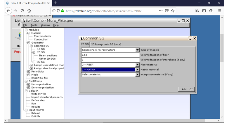
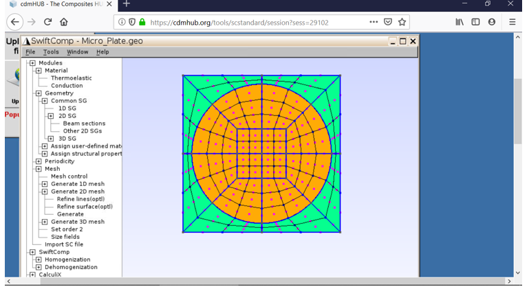
Go to Geometry select 2D SG and choose Other 2D SGs and in the pop up window, set the Type of models as Square Pack Microstructure. Modify the Volume fraction of the fiber accordingly and set the Fiber material and Matrix material as required and Add. Close the Window.
 Creating geometry
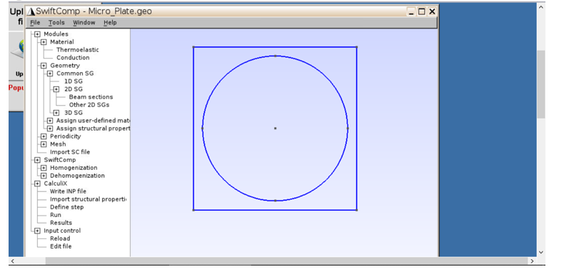 Creating geometry
1.4 Setting the mesh
Go to Mesh select Generate 2D mesh and choose Generate. To get a finer mesh, go to Input control, click on Edit file and in the pop up window and scroll down to the three Transfinite line commands and increase their value by the factor you wish to increase your mesh. In this example the mesh is increased by a factor of three. Then save the changes in the window and exit it. Generate the mesh again.
 Meshing the model
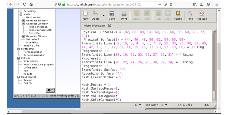 Meshing the model
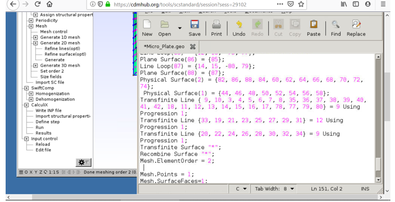 Meshing the model
Meshing the model
1.5 Homogenization
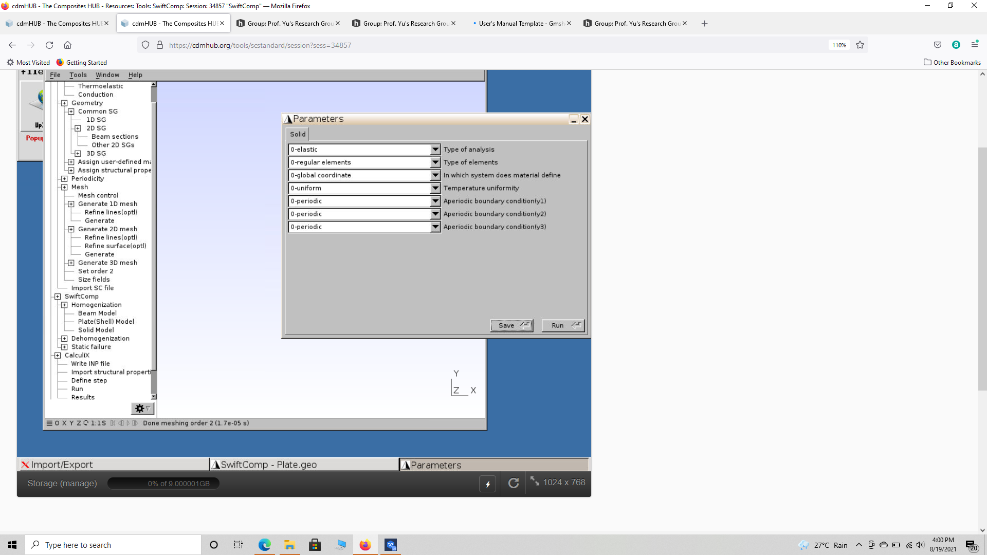
Go to SwiftComp and select Homogenization, and in the window keep the preset options, save the model and run it. The homogenized results will be displayed in a new pop up window.
Homogenization
Microscale Results
1.6 Save the results using an fttp app or note the for the next step.
2) Elastic homogenization of the layup (stack of oriented plates), using Gmsh4SC.
2.1 Open a new model
Go to File select New and save the model as shown previously.
2.2 Assigning the material properties:
Go to Material select Thermoelastic and in the pop up window choose the material type. Use the approximated Orthotropic engineering constants or use the stiffness matrix (more accurate) from the microscale analysis to enter the material properties, then select Add.
 Assigning matrix material properties
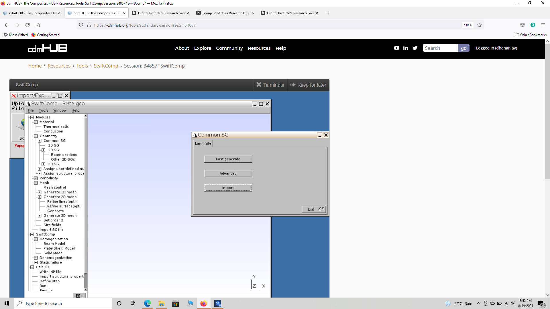
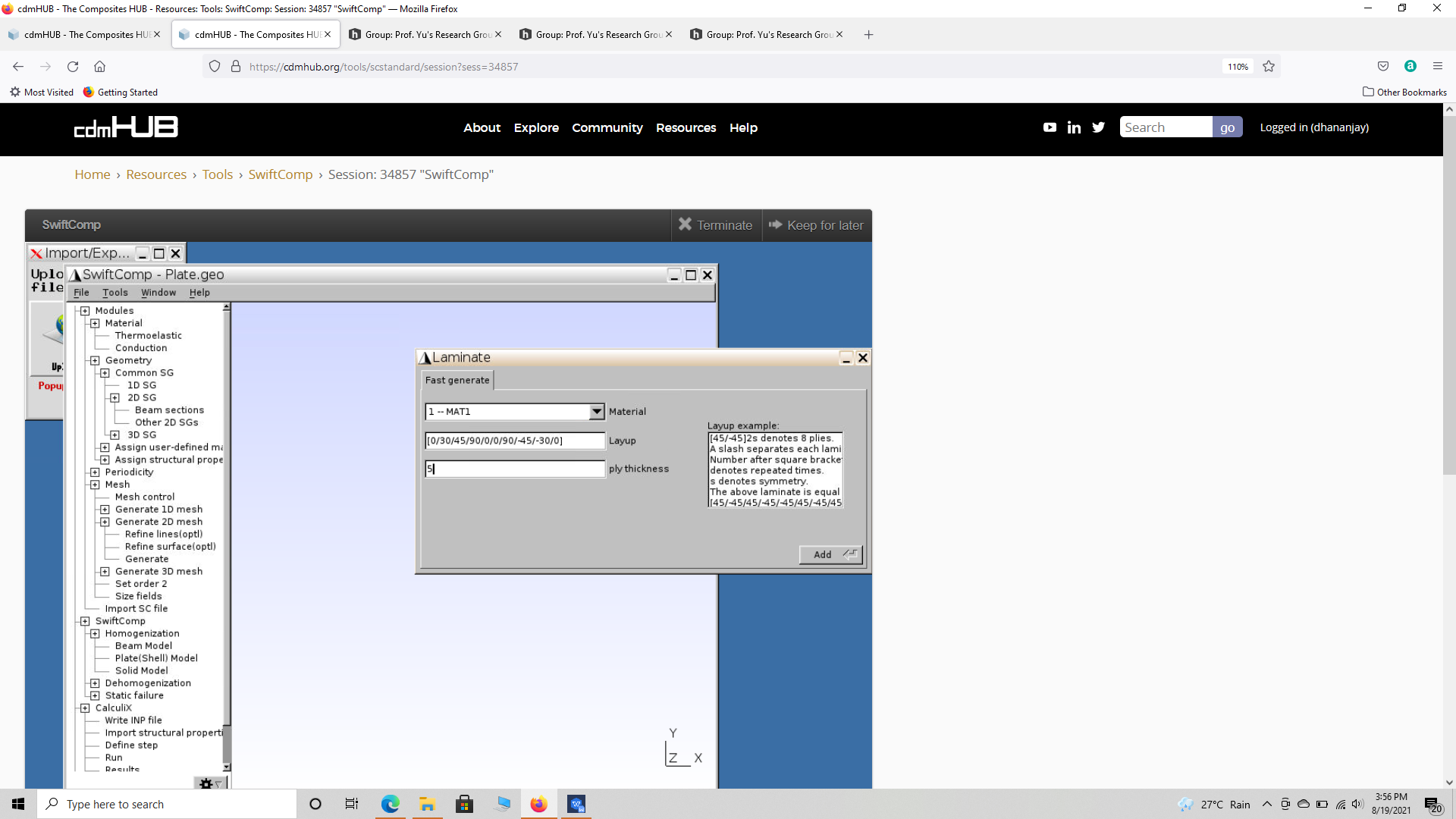
2.3 Creating geometry
Go to Geometry select 1D SG, choose fast generate and enter the layup as (0/30/45/90/0/0/90/-45/30/0), but use the square bracket to enter the layups.
 Creating plate SG geometry
 Creating plate SG geometry
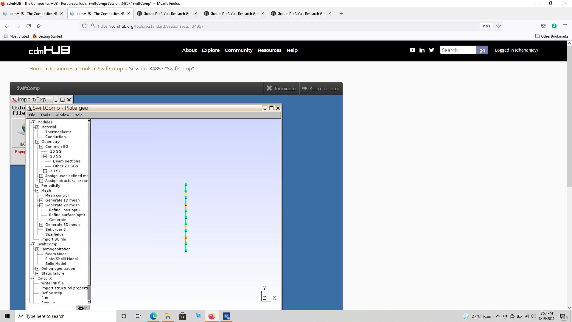 Creating layup SG geometry
2.4 Setting the mesh
Go to Mesh select Generate 1D mesh and choose Generate.
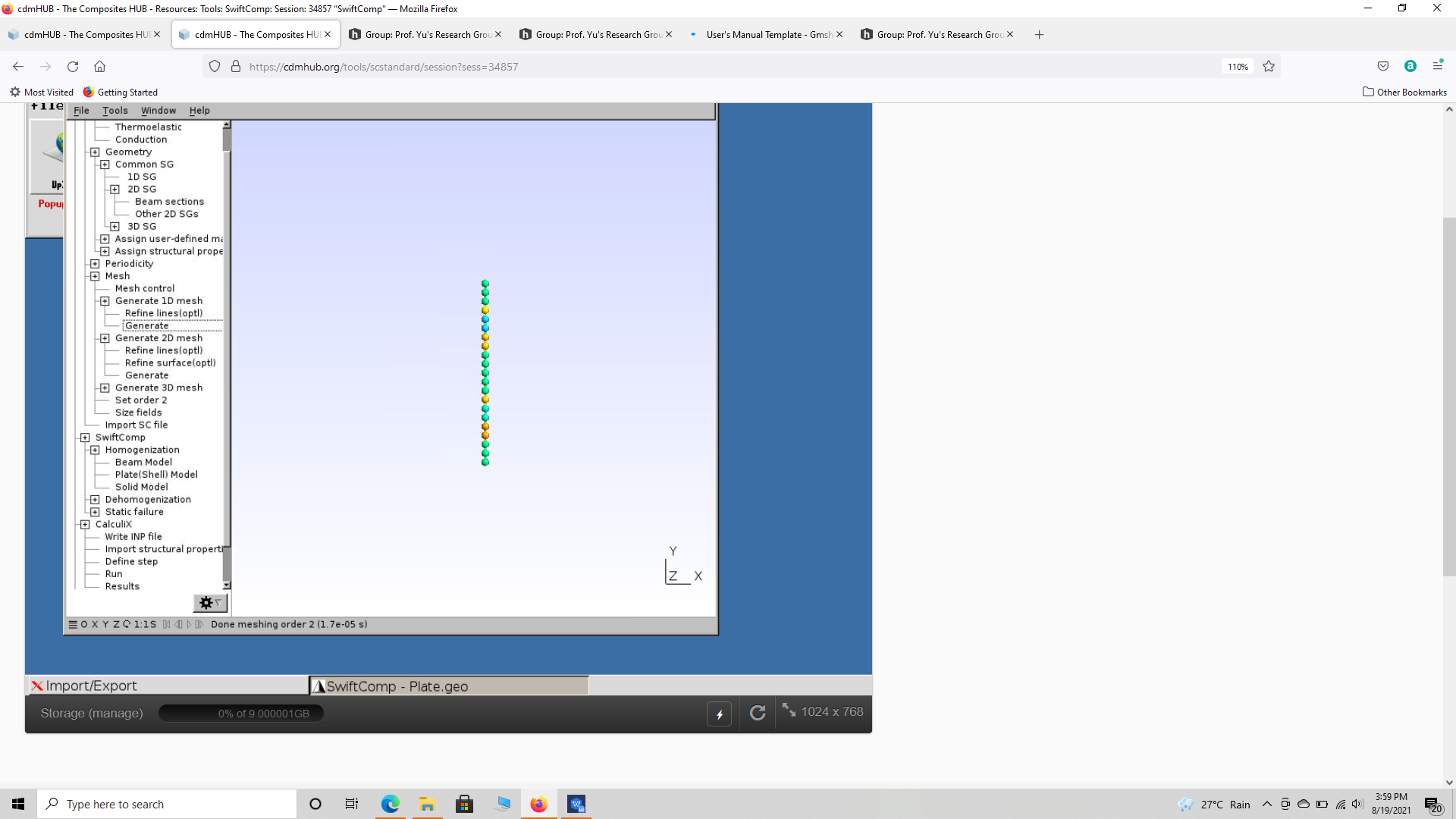 Creating layup SG mesh
2.5 Homogenization
Go to SwiftComp and select Homogenization, and in the window keep the preset options, save the model and run it. The homogenized results will be displayed in a new pop up window.
 Homogenization of the layup
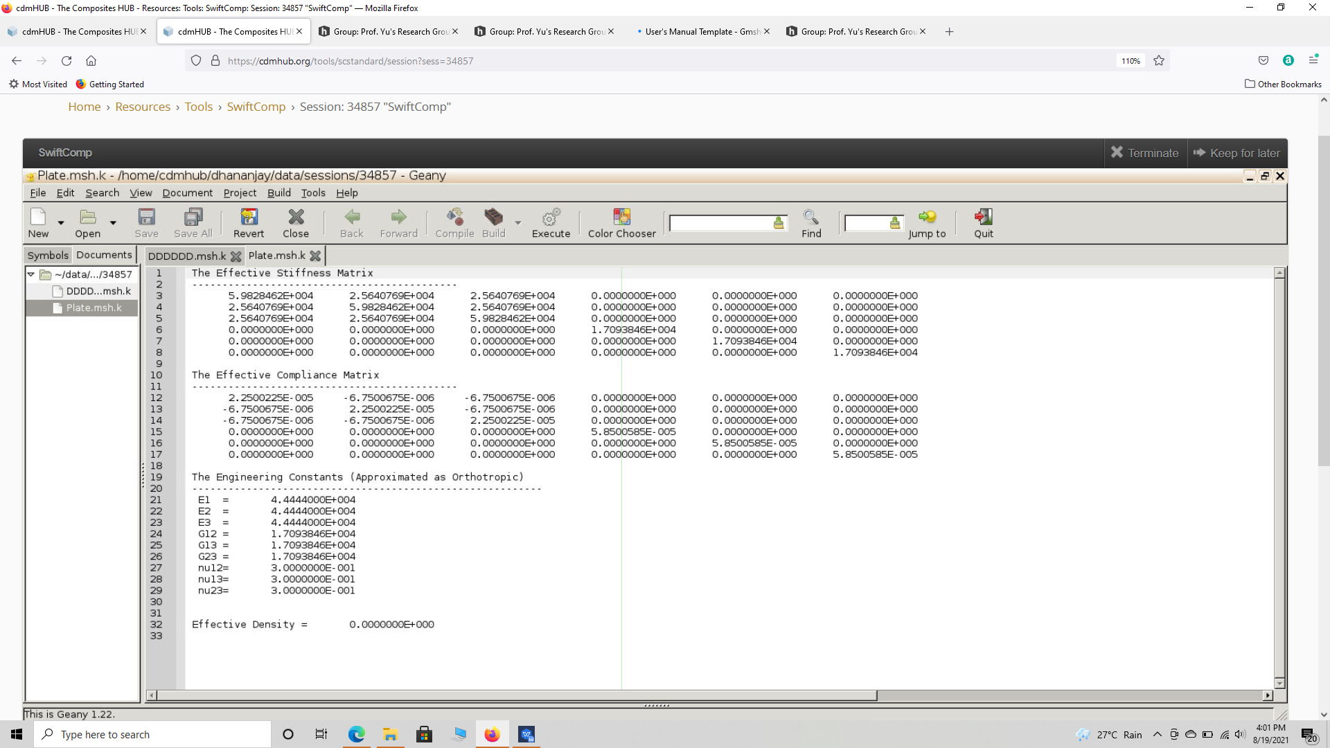 Results of layup homogenization
3) Modeling of the Nacelle component in Abaqus as a homogeneous body.
# Step 3.1.Create the 3d part shown below using conventional abaqus methodology. Notice we model the nacelle as a 3D homogeneous part. Ensure the part is partition as shown to add the material properties later. The half section of the part is also shown.
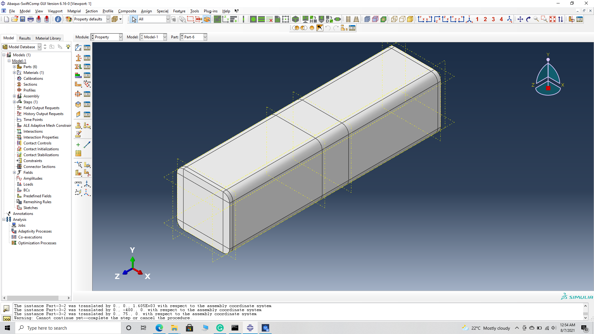 Nacelle shell
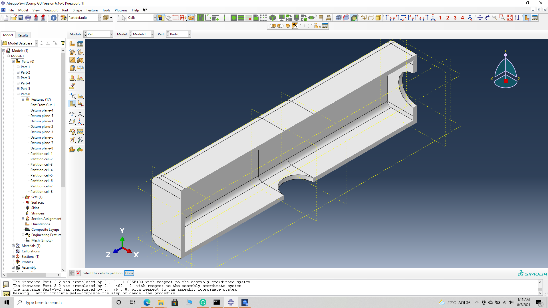 Nacelle shell half section
# Step 3.2.’ Enter the material properties for the model. First we need to choose the material properties from the results of the computed effective elastic properties in the previous part. Then we need to convert the Constitutive relations provided as SwiftComp’s results into Abaqus’s Constitutive relations. This can be done by switching the 4th and 6th rows for the relation and also switching the 4th and 6th column of the stiffness matrix. The relations are provided below. Within the Materials section of Abaqus CAE, we create a material called “Material-1” and add the corresponding properties. We can also import the homogenized properties from the toolbar if we have downloaded the property file from the previous step..
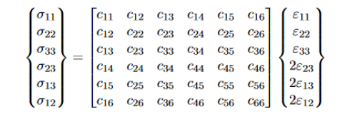
 Abaqus's Constitutive relations
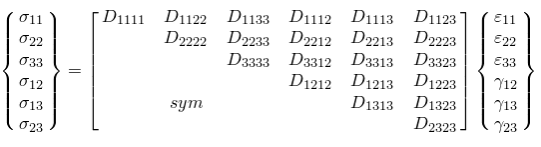
 SwiftComp's Constitutive relations
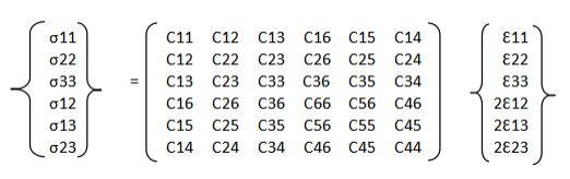 SwiftComp's output Constitutive relations converted into Abaqus's input Constitutive relations
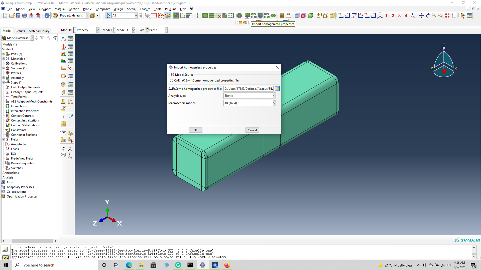 Importing Material properties
# Step 3.3.’ Create an anisotropic elastic material and add the homogenized material properties as explained in the previous step. Create and assign a section to the part.
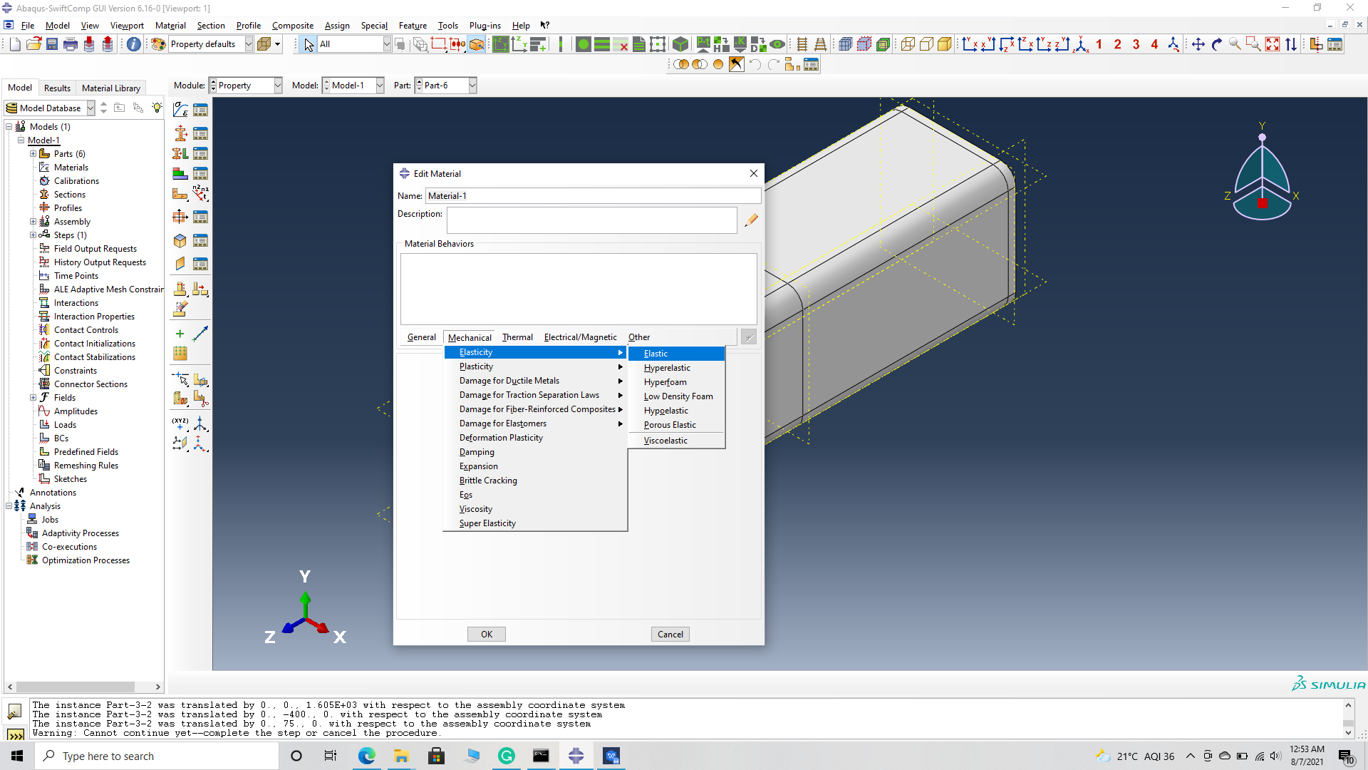 Create an anisotropic elastic material
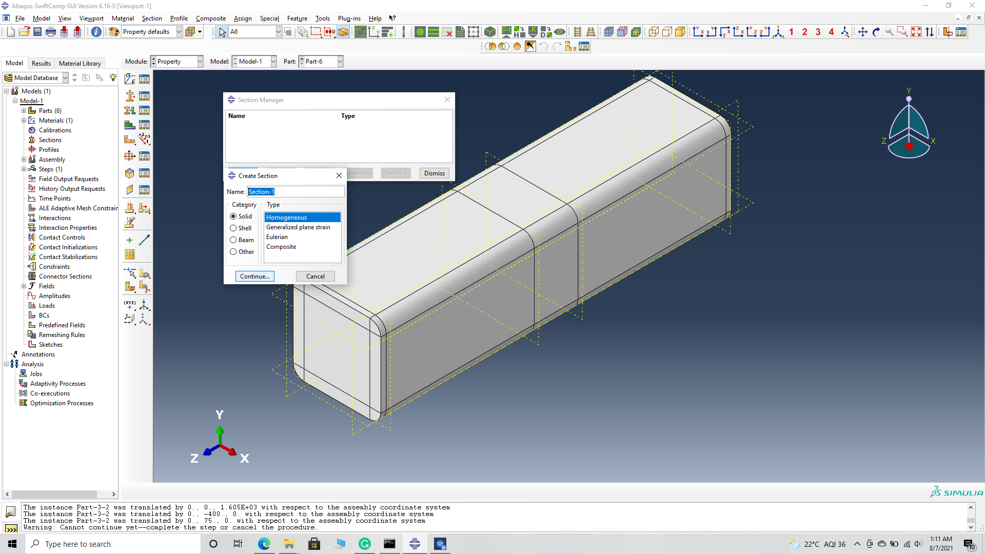 Create a section
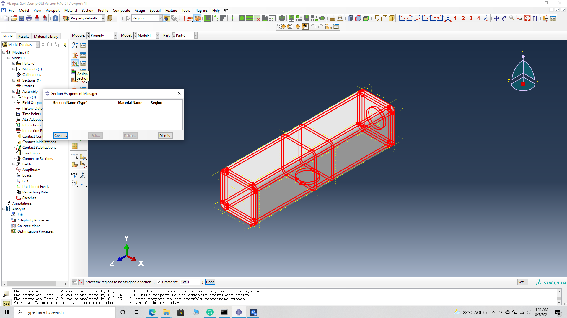 assign the section
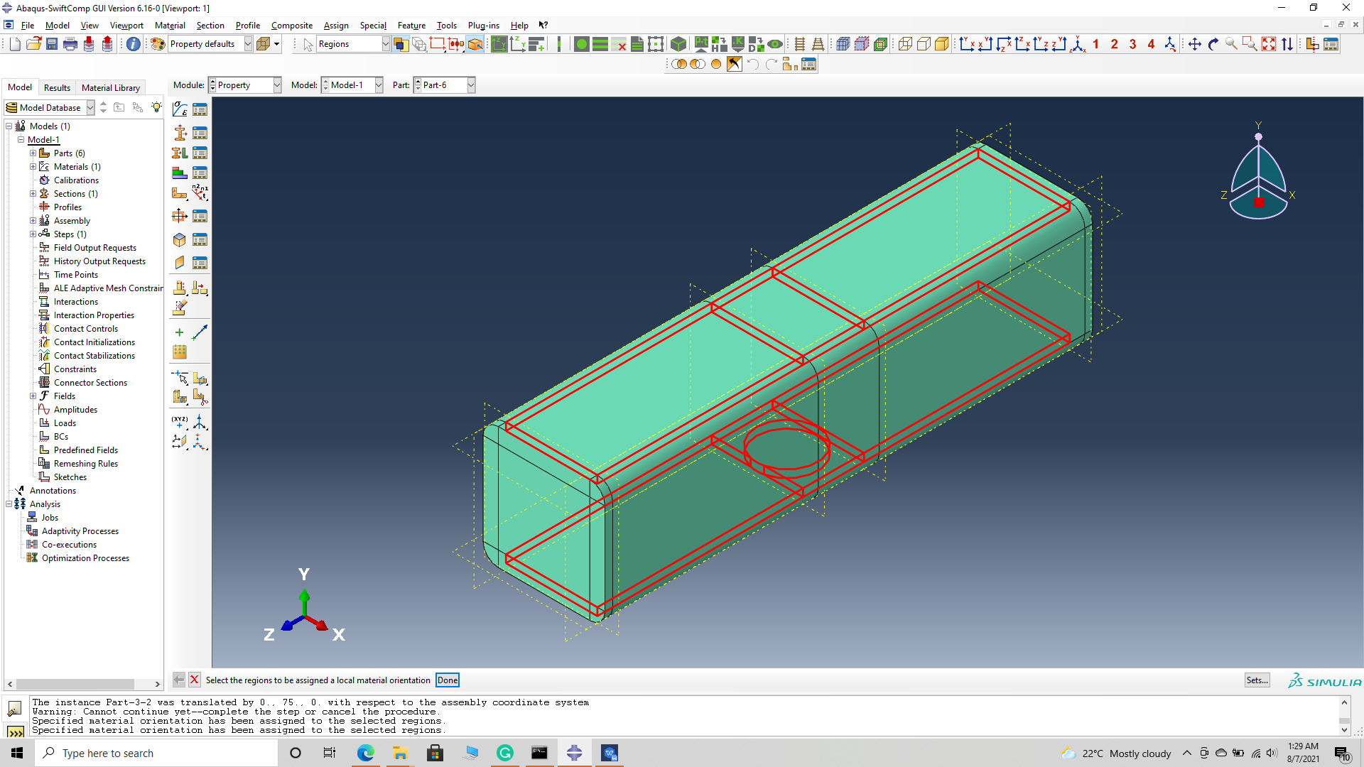
‘ # Step 3.4. Now we assign the material orientation for the part. Go to Assign material orientation -> select the end sections of the part and -> Done -> Select a CSYS (use default orientation or other method) -> set the global orientation to both as shown. They will have opposite orientation if the plies are symmetric. But we are not using symetric model for the nacelle. -> Done –
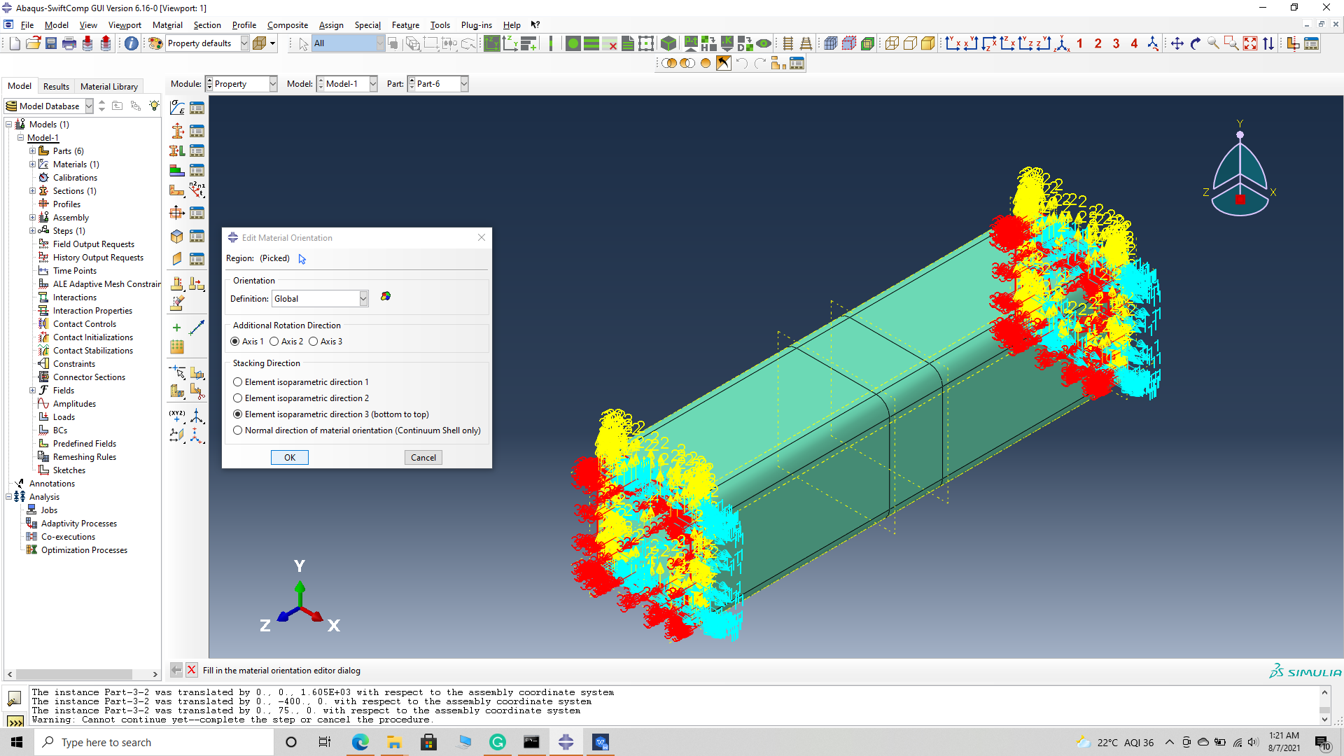 Assign material orientation
(Image(N3.42.png, desc="Assign material orientation") failed - File not found)
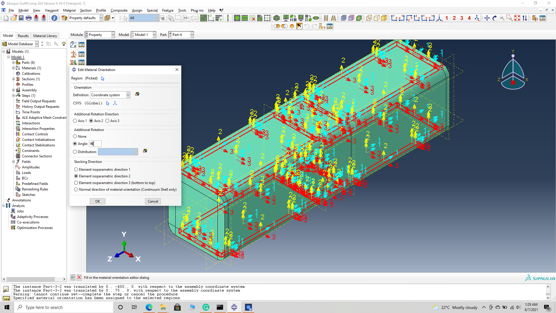
‘ # Step 3.5. Select the top and bottom sections of the part and -> Done -> Select a CSYS (use default orientation or other method) -> set the Coordinate system orientation to both as shown. -> Define -> addition axis of rotation -> axis 2 as 90 degree -> Continue -> OK -> Done –
 Assign material orientation
 Assign material orientation
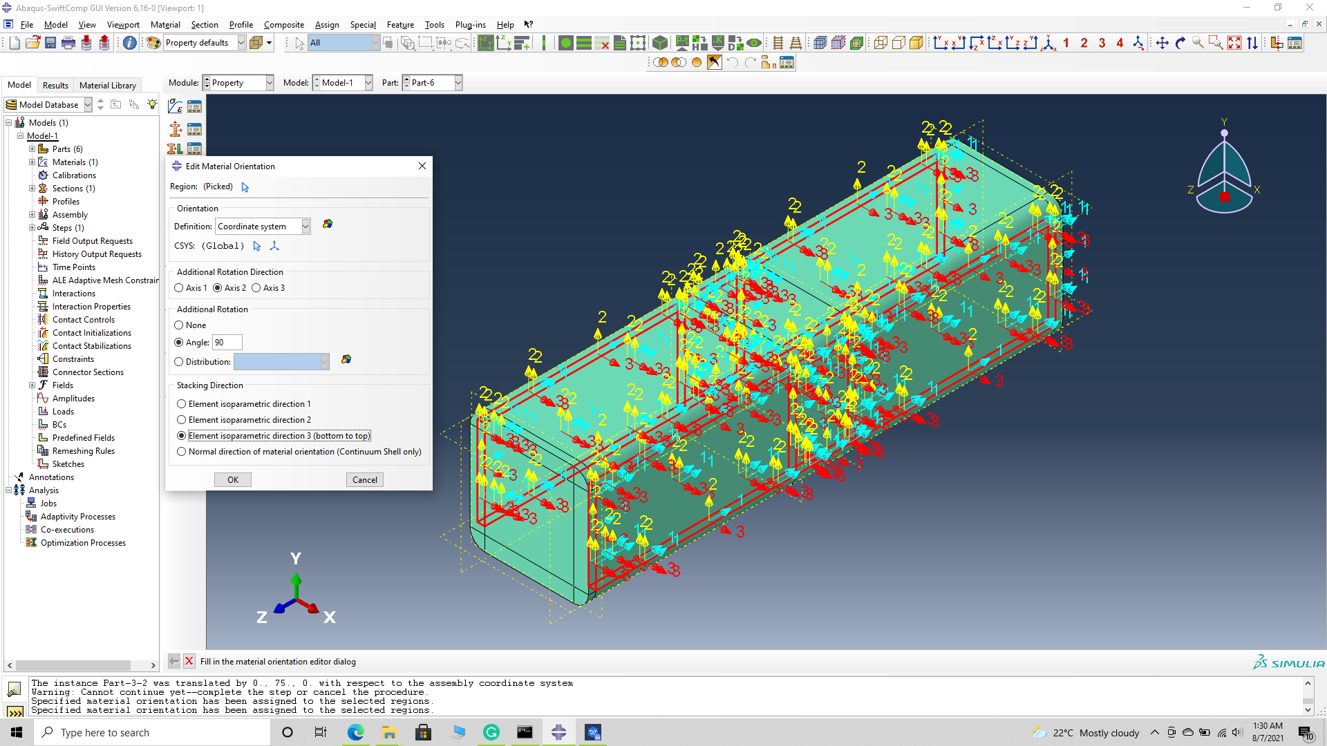
# Step 3.6. Select the side sections of the part and -> Done -> Select a CSYS (use default orientation or other method) -> set the Coordinate system orientation to both as shown. -> Define -> addition axis of rotation -> axis 2 as 90 degree -> Continue -> OK . -> Done –
 Assign material orientation
 Assign material orientation
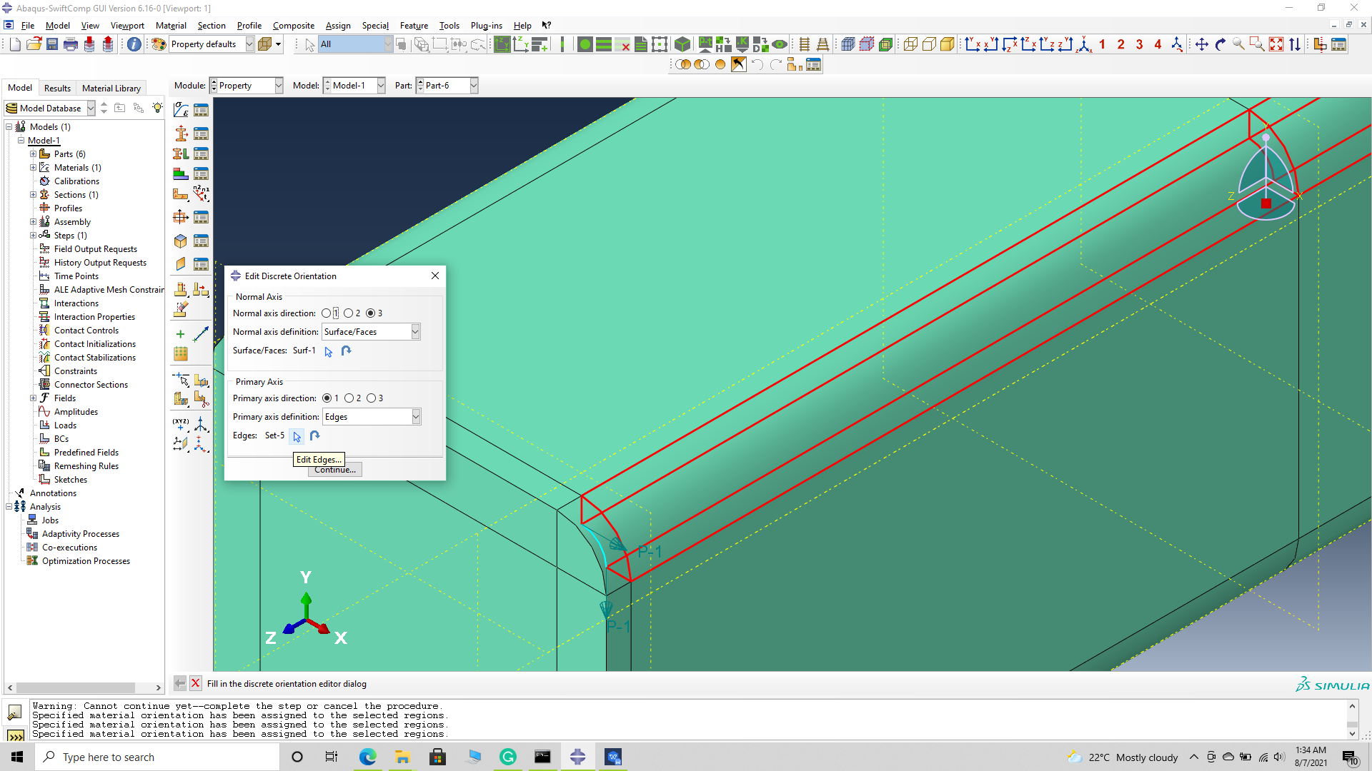
# Step 3.7. Select the top right curved sections of the part and -> Done -> Select a CSYS (use default orientation or other method) -> set the discrete orientation as shown. -> Define -> Primary axis orientation -> choose edge and flip direction if needed to make the axis point towards a clockwise direction -> Choose the surfaces for the normal axis definition -> Continue -> OK -> Done –
 Assign material orientation
 Assign material orientation
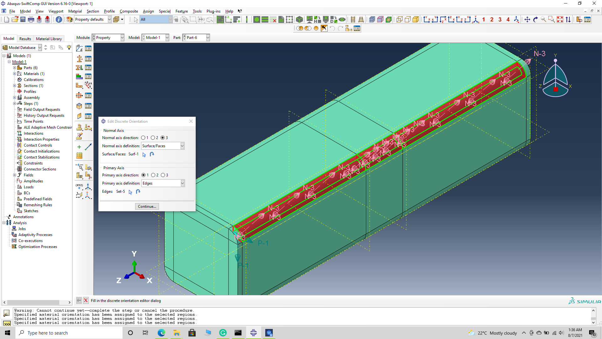 Assign material orientation
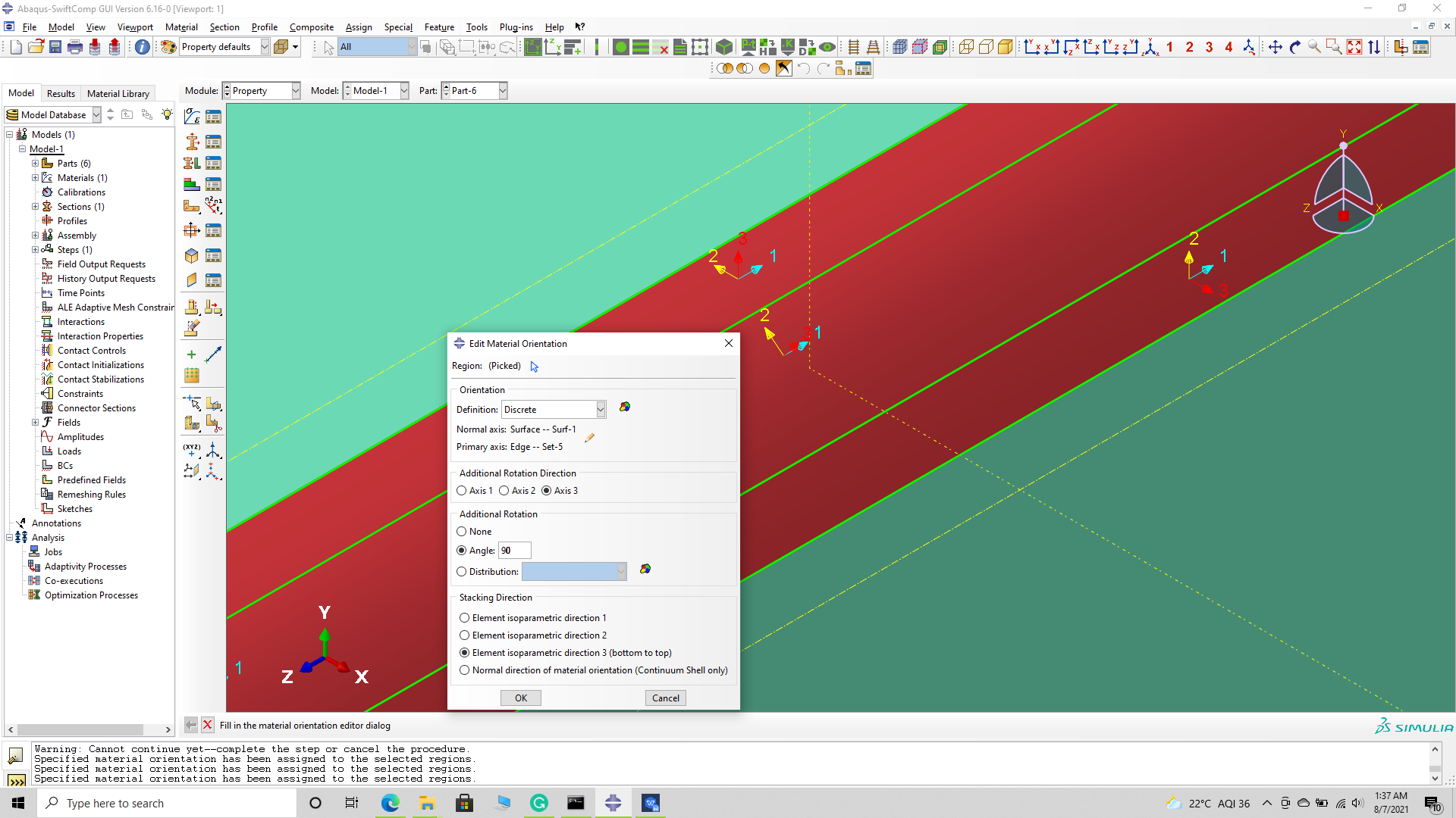 Assign material orientation
# Step 3.8. Select the bottom right curved sections of the part and -> Done -> Select a CSYS (use default orientation or other method) -> set the discrete orientation as shown. -> Define -> Primary axis orientation -> choose edge and flip direction if needed to make the axis point towards a clockwise direction -> Choose the surfaces for the normal axis definition -> Continue -> OK -> Done –
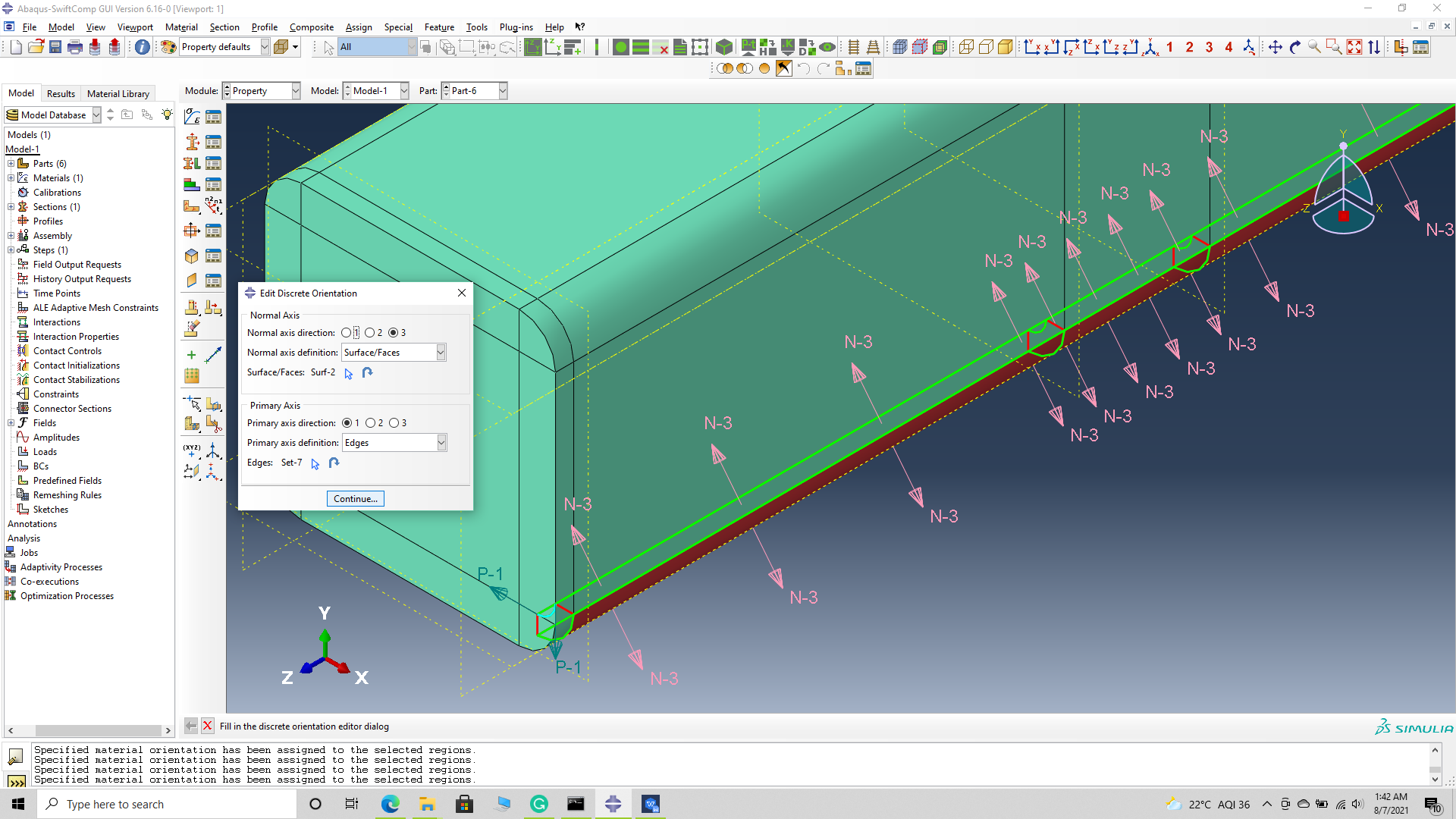 Assign material orientation
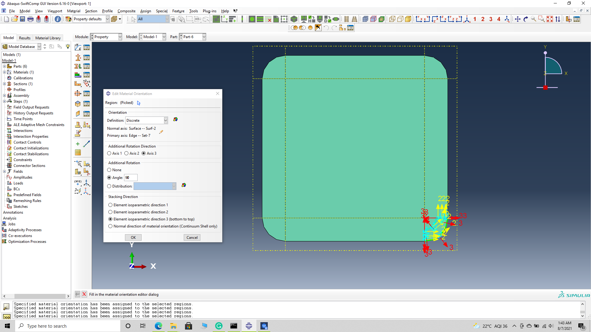 Assign material orientation
Assign material orientation
# Step 3.9. The final orientation should look like this
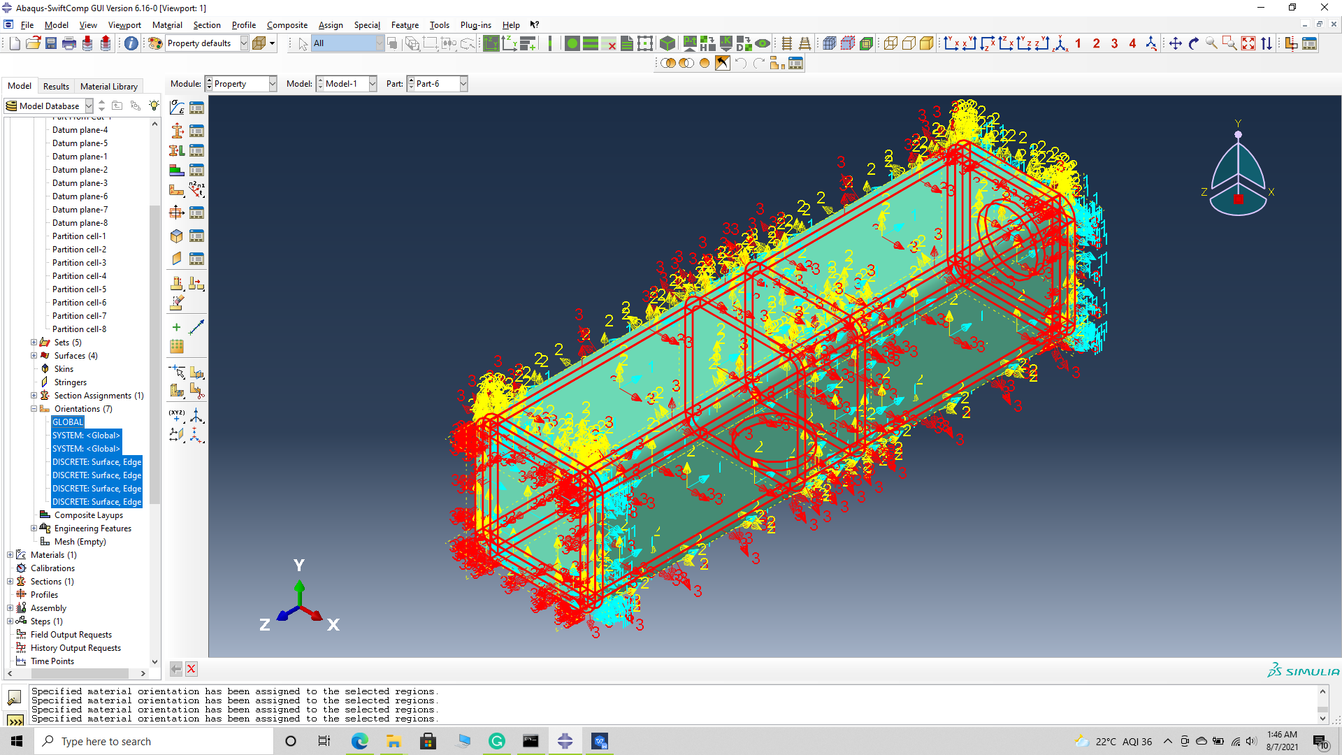 Assign material orientation
# Step 3.10. Mesh the part and continue with the traditional structural analysis with reduced mesh elements.
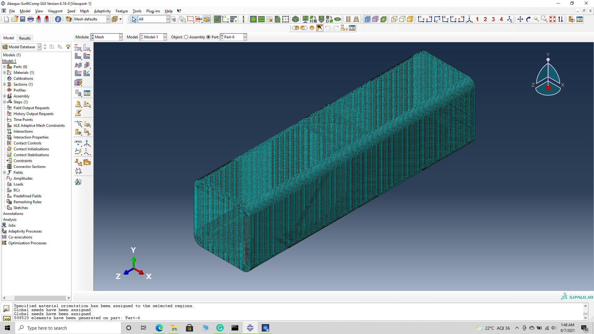 Assign material orientation