Elastic Beam Properties of a Lenticular Boom
This tutorial shows how to calculate cross-sectional properties of the Lenticular boom with given dimensions and material properties using SwiftComp 1.3 and PreVABS.
Flattened height: 45 mm, Web height(one side): 3 mm, Subtended angle: 90 degree, Ply thickness: 0.04 mm,
Radius of the flange (curved part): 6.21 mm,
Layup: (30)2 . The layup sequence is along with the direction pointing to the center of flange(Blue arrow).
Material properties
E1 = 174.4 GPa, E2 = E3 = 8.39 GPa, G12 = G13 = 6.4 GPa, G23 = 3.2 GPa, v12 = ν13 = 0.259, ν23 = 0.3.
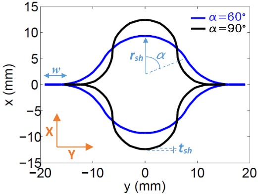
Figure.1
Software Used
SwiftComp 1.3 and PreVABS
Solution Procedure
The input files for PreVABS are prepared in XML format based on all the design parameters given above. A brief summary of the input files is given below:
• A baseline file (baselines_len.xml), storing definitions of geometry.
• A material file (MaterialDB.xml), storing definitions of materials and laminae.
• A layup file (layups_len.xml), storing definitions of layups.
• A main cross-section file (boom_len.xml), storing definitions of components and other configurations of modelling and analysis.
All files can have file names of user’s choice and can be placed at any working directory.
Step 1: Preparing the baseline file (baselines_len.xml)
Basepoints: The fifteen points from p0 to p14 are used to define the geometry of the model. Points p1 and p2 define the top web, while p7 and p9 define the bottom web. Points p2, p3, p4, p5, p6, p7 and p8 define the right flange and p2, p13, p11, p14, p12, p10 and p7 define the left flange. Point p0 is taken as the origin of the coordinate system. The coordinates of the points are obtained from simple geometric calculations. Base lines are created based on key points defined above. The direction of each base line is important. It is related with how the laminate is created for each segment, and how the local coordinate system is defined for each element. As shown in Figure 2 two straight lines and six arcs are used to define the cross-section of the boom. The straight line line_1 is defined by points p1 and p2. The arc line_2 is defined by p2 as starting point, p3 as end point, p4 as center and its direction is set as counter clockwise. Similarly the other straight line and arcs are defined by the base points and direction.
Refer to the prevabs manual for more details on input file generation.
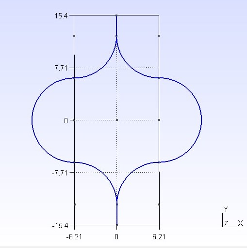
Figure.2
Input file for geometric elements (baseline_len.xml).
<baselines>
  <basepoints>
    <point name="p0">0 0</point>
    <point name="p1">0 15.42</point>
    <point name="p2">0 12.42</point>
    <point name="p3">6.21 6.21</point>
    <point name="p4">6.21 12.42</point>
    <point name="p5">6.21 0</point>
    <point name="p6">6.21 -6.21</point>
    <point name="p7">0 -12.42</point>
    <point name="p8">6.21 -12.42</point>
    <point name="p9">0 -15.42</point>
    <point name="p10">-6.21 -12.42</point>
    <point name="p11">-6.21 -6.21</point>
    <point name="p12">-6.21 0</point>
    <point name="p13">-6.21 6.21</point>
    <point name="p14">-6.21 12.42</point>
  </basepoints>
  <baseline name="line_1" type="straight">
    <points>p1,p2</points>
  </baseline>
  <baseline name="line_2" type="arc">
    <center>p4</center>
    <start>p2</start>
    <end>p3</end>
    <angle>90</angle>
    <direction>cw</direction>
  </baseline>
  <baseline name="line_3" type="arc">
    <center>p5</center>
    <start>p3</start>
    <end>p6</end>
    <direction>cw</direction>
  </baseline>
  <baseline name="line_4" type="arc">
    <center>p8</center>
    <start>p6</start>
    <end>p7</end>
    <direction>ccw</direction>
  </baseline>
  <baseline name="line_5" type="straight">
    <points>p7,p9</points>
  </baseline>
  <baseline name="line_6" type="arc">
    <center>p10</center>
    <start>p11</start>
    <end>p7</end>
    <direction>cw</direction>
  </baseline>
  <baseline name="line_7" type="arc">
    <center>p12</center>
    <start>p13</start>
    <end>p11</end>
    <direction>ccw</direction>
  </baseline>
  <baseline name="line_8" type="arc">
    <center>p14</center>
    <start>p2</start>
    <end>p13</end>
    <direction>cw</direction>
  </baseline>
</baselines>
Step 2: Preparing the material file (MaterialDB.xml)
Material data is stored in the material database. Arrangements of data are different for different material types, which can be isotropic, orthotropic, or anisotropic. Another part of the file is the lamina data. A lamina is a unique combination of material and ply thickness. It is the lamina, instead of the material, that will be used to define each layer of the layup. The lamina defined here is named la2 with thickness 0.04 mm.
Input file for materials (MaterialDB.xml).
<materials>
   <material name="mr60h_ud_lee2019" type="orthotropic">
    <density>1</density>
    <elastic>
      <e1>174.4e3</e1>
      <e2>8.39e3</e2>
      <e3>8.39e3</e3>
      <g12>6.4e3</g12>
      <g13>6.4e3</g13>
      <g23>3.2e3</g23>
      <nu12>0.259</nu12>
      <nu13>0.259</nu13>
      <nu23>0.3</nu23>
    </elastic>
   </material>
   <lamina name="la2">
    <material>mr60h_ud_lee2019</material>
    <thickness>0.040</thickness>
   </lamina>
</materials>
Step 3: Preparing the layup file (layups_len.xml)
Layup information is stored in a separate file and the main input file calls upon the layup file to define the laminate, named here as layup_2. The order of the layers defines the laying sequence from the base line. The number in the element stands for the orientation of the lamina.
Input file for layups (layups_len.xml).
<layups>
  <layup name="layup_2">
    <layer lamina="la2">30</layer>
    <layer lamina="la2">30</layer>
  </layup>
</layups>
Step 4: Preparing the main cross-section file (boom_len.xml)
The main input file of the cross-section contains several required or optional settings along with the definitions of components.
• The first part is the settings, which is required. This contains the baselines and layups files.
• The second part is the settings, which is optional. This contains configurations used by SwiftComp for the cross-sectional analysis. For this example, the setting is set to 0, which means that the Euler-Bernoulli beam model will be used and the 4 by 4 stiffness matrix will be calculated.
• The third part is the settings, which is optional. This part contains global configurations for the shape and meshing of the cross-section. Here, the global mesh size is set to 0.03.
• The fourth part is the component definition. Each laminate-type component is composed of one or more segments. Each segment is a unique combination of a base line and a layup. The layup can be created on either side of the base line. This is controlled by an attribute “direction”, which can be either left or right while moving along the baseline. The component on the right side, right_part is defined by five segments formed by baselines line_1, line_2, line_3, line_4 and line_5, and is assigned the direction “left”. Similarly the component on the left side, left_part is defined by five segments formed by baselines line_1, line_8, line_7, line_6 and line_5, and is assigned the direction “right”.
Input file for the cross-section (boom_len.xml).
<cross_section name="boom_len">
  <include>
    <baseline>baselines_len</baseline>
    <layup>layups_len</layup>
  </include>
  <analysis>
    <model>0</model>
  </analysis>
  <general>
    <mesh_size>0.02</mesh_size>
  </general>
  <component name="right_part">
    <segment name="part_1">
      <baseline>line_1</baseline>
      <layup direction="left">layup_2</layup>
    </segment>
    <segment name="part_2">
      <baseline>line_2</baseline>
      <layup direction="left">layup_2</layup>
    </segment>
    <segment name="part_3">
      <baseline>line_3</baseline>
      <layup direction="left">layup_2</layup>
    </segment>
    <segment name="part_4">
      <baseline>line_4</baseline>
      <layup direction="left">layup_2</layup>
    </segment>
    <segment name="part_5">
      <baseline>line_5</baseline>
      <layup direction="left">layup_2</layup>
    </segment>
  </component>
  <component name="left_part">
    <segment name="part_6">
      <baseline>line_1</baseline>
      <layup direction="right">layup_2</layup>
    </segment>
    <segment name="part_7">
      <baseline>line_8</baseline>
      <layup direction="right">layup_2</layup>
    </segment>
    <segment name="part_8">
      <baseline>line_7</baseline>
      <layup direction="right">layup_2</layup>
    </segment>
    <segment name="part_9">
      <baseline>line_6</baseline>
      <layup direction="right">layup_2</layup>
    </segment>
    <segment name="part_10">
      <baseline>line_5</baseline>
      <layup direction="right">layup_2</layup>
    </segment>
  </component>
</cross_section>
Step 5: Execution and Results
Once all input files are prepared, the cross-section can be created and homogenized using the following procedure:
• Open the command line window and change directory to the root of the working directory.
• Type the following command:
prevabs –sc –i boom_len.xml -h -v -e
If everything works successfully, Gmsh will be called and the cross-section will be plotted as shown in Figure 3 and SwiftComp homogenization analysis will be carried out and effective beam properties can be found in the file boom_len.sg.K.
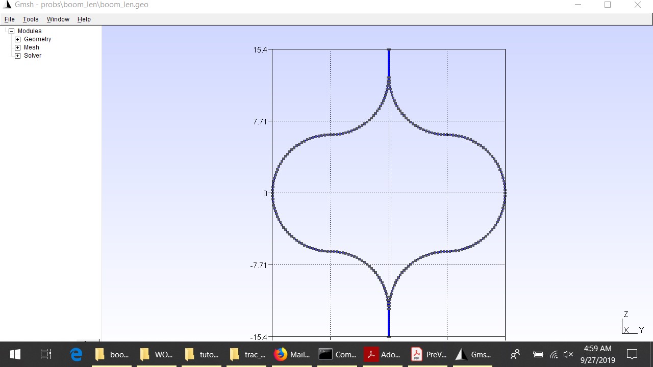 Figure.3
The effective stiffness matrix:
| 1.8274E+05 | 0 | 0 | 0 |
| 0 | 6.9092E+06 | 0 | 7.5931E+06 |
| 0 | 0 | 1.2252E+07 | 0 |
| 0 | 7.5931E+06 | 0 | 1.7606E+07 |