Elastic properties of a chopped fiber reinforced composite
In this example, we want to compute the elastic properties of a chopped fiber reinforced composite made of isotropic elastic matrix and transversely isotropic elastic fiber. The MSG solid model is used to predict the effective elastic properties of the 3D SG.
We will consider a matrix cell of dimensions 10 mm x 10 mm x 10 mm and ten chopped fibers of radius 1 mm and length 8 mm to have a fiber volume fraction of 0.25. The fiber and matrix material properties are given in the table below.
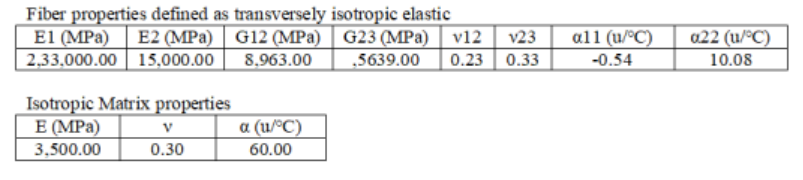 Material Properties
The orientation of the individual fibers with respect to the origin of the model are given in terms for translation coordinates and rotational degrees for all three axes in the table below.
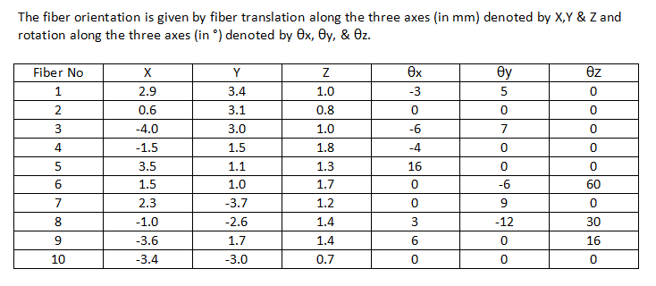 Fiber orientation
Software Used
We will use SwiftComp 2.1 and Abaqus CAE with the Abaqus SwiftComp GUI for this tutorial. Abaqus CAE will be used to model the 3D SG while SwiftComp will be used to run the elastic homogenization in the background.
Solution Procedure
The problem is solved in the following steps:
We will first create the matrix cell.
# Step 1. Go to create part -> Create a 3D solid extrusion -> Sketch the cross section as a 10 mm x 10 mm square with the origin at the center. Extrude the part to a length of 10 mm so the origin is at the center of one side. This will help in the assembly.
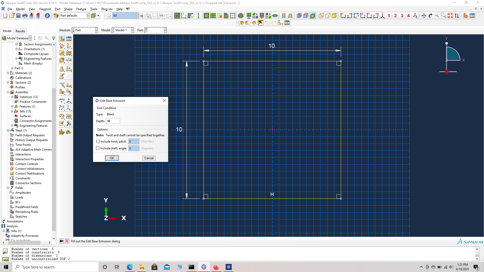 Part dimensions
 Part Geometry
# Step 2. Enter the material properties for the model. First we need to choose the material properties from the matrix property table. Within the Materials section of Abaqus CAE, we create a elastic isotropic material called “Matrix” and add the corresponding properties.
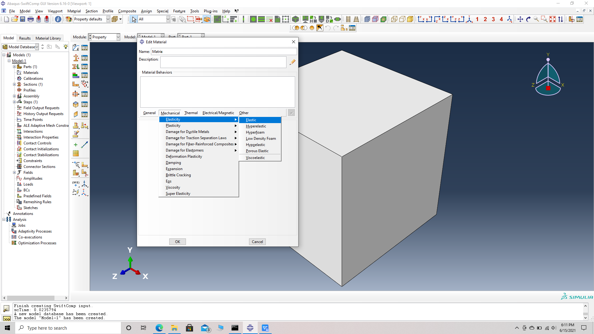 Material properties
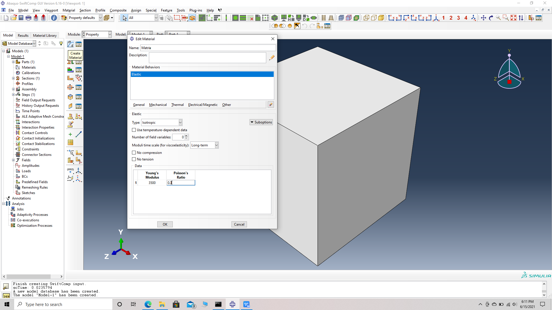 Material properties
# Step 3. Create a homogeneous section, Section 1 for the matrix using the create section option.
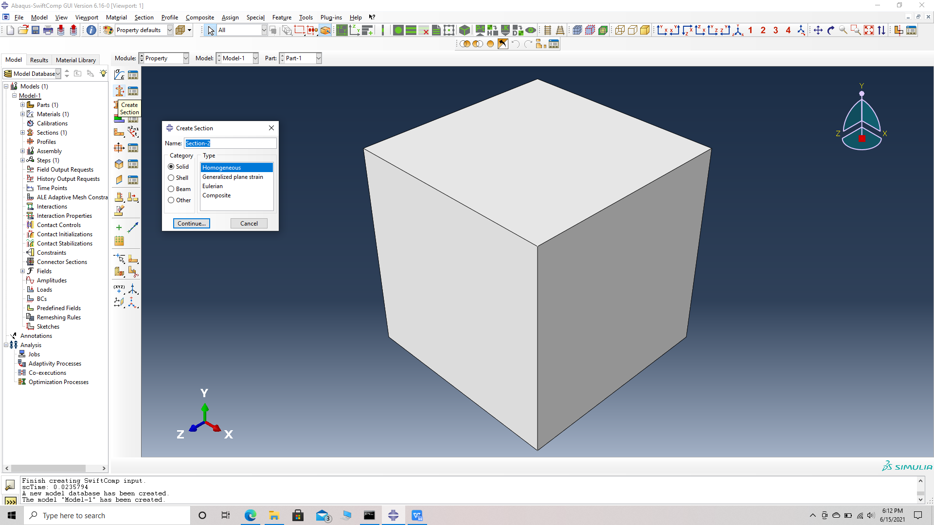 Create a section
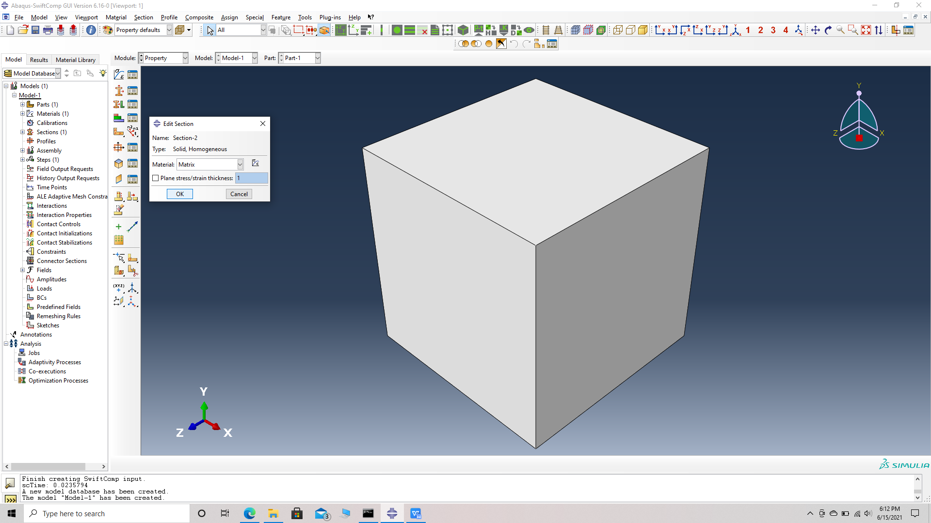 Assigning the material Matrix
# Step 4. Assign the section , Section 1 for the matrix cell using the assign section option. Name the set as Set-111 to differentiate different sets for different parts. Abaqus automatically assigns set- name for all parts as Set -1.
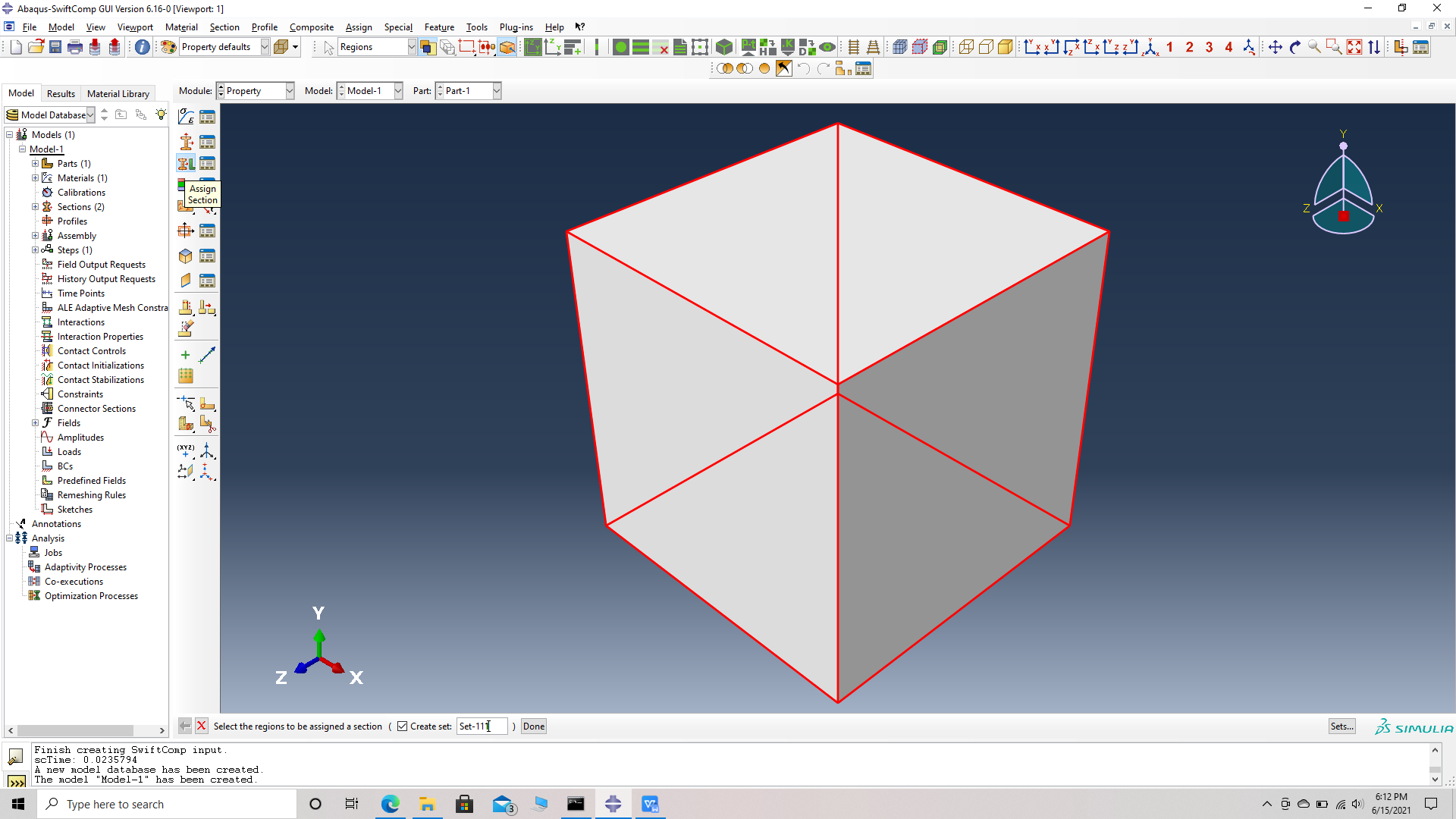 Assign a set
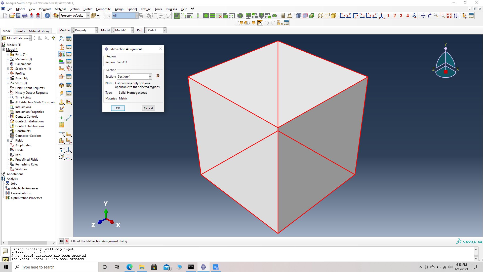 Assign Section for Set
We will first create the chopped fiber
# Step 5. Go to create part -> Create a 3D solid extrusion -> Sketch the cross section as a circle of radius 1 mm with the origin at the center. Extrude the part to a length of 8 mm so the origin is at the center of one side. This will help in the assembly.
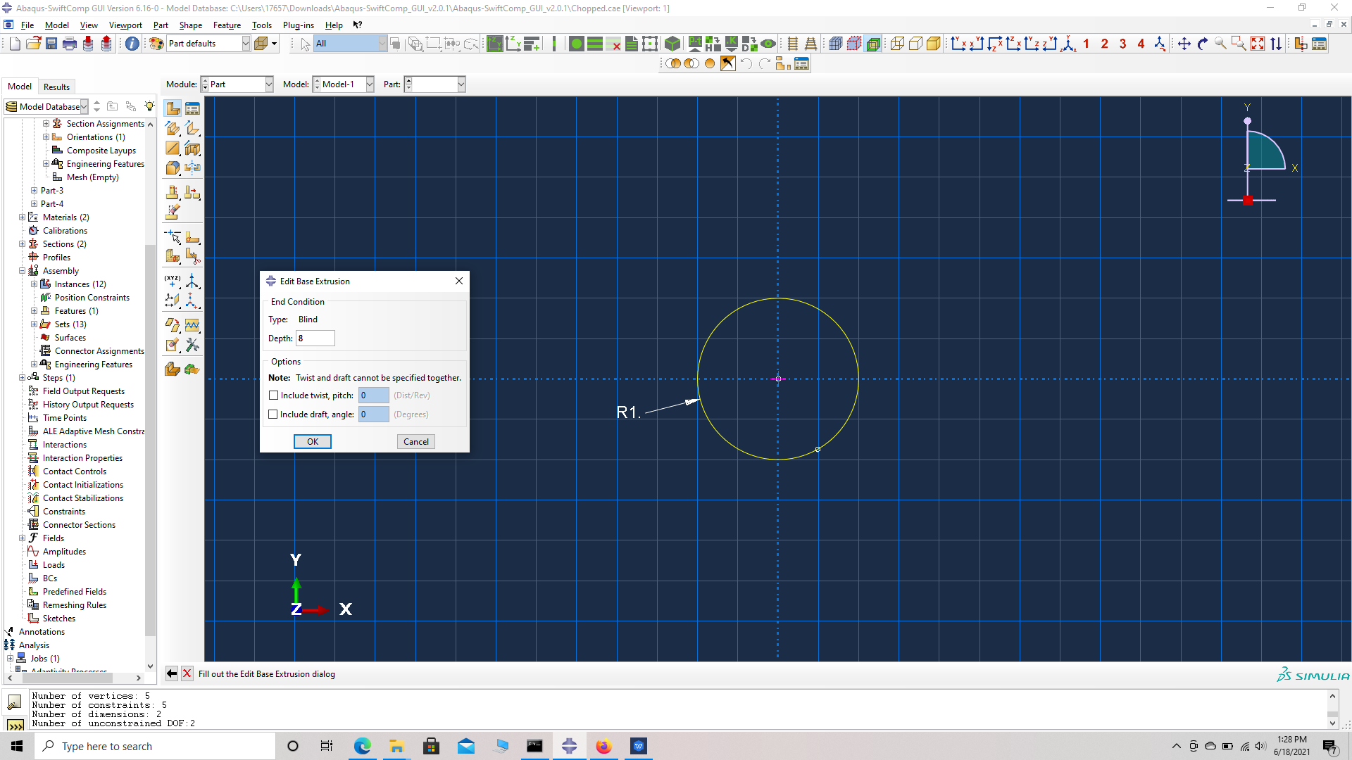 Part dimensions
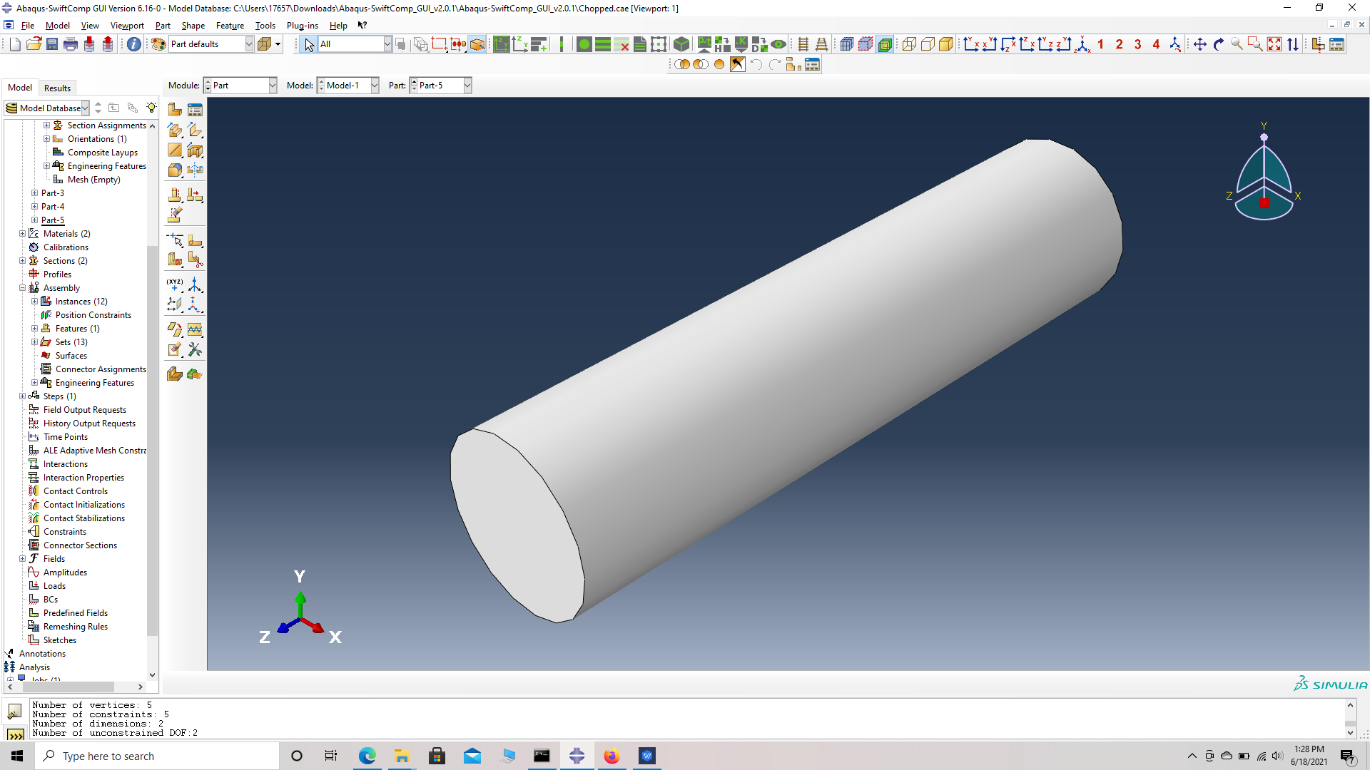 Part Geometry
# Step 6. Enter the material properties for the model. First we need to choose the material properties from the fiber property table. Within the Materials section of Abaqus CAE, we create a elastic material called “Fiber” and add the corresponding properties s engineering constants.
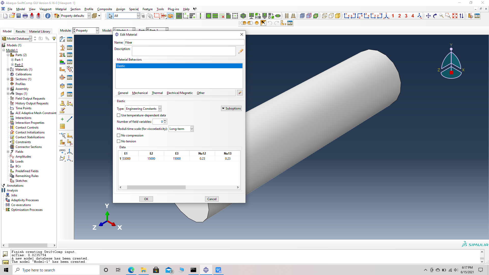 Material properties
# Step 7. Create a solid homogeneous section, Section 2 for the fiber using the create section option.
# Step 8. Assign the section , Section 2 for the fiber using the assign section option. Name the set as Set-22 to differentiate different sets for different parts. Abaqus automatically assigns set- name for all parts as Set -1.
 Assign a set to the model
 Assign the Section for Set
# Step 9. Create a local material coordinate system for the fiber. This is done because, the material coordinates of the fiber do not align with the global material coordinates. Create a datum CSYS with three points-> select a rectangular system -> choose the origin which is also the center of a face of the fiber cylinder, as the first point i.e a point on the origin-> choose the center of the opposite face as the second point, i.e a point on the x axis -> choose a point on the circumference of the opposite face whose center is the second point, i.e a point on the x-y plane -> create datum. Note we can randomly chhose a point on the second surface to be a point on the x-y plane if the material properties along the y and z axes are equal.
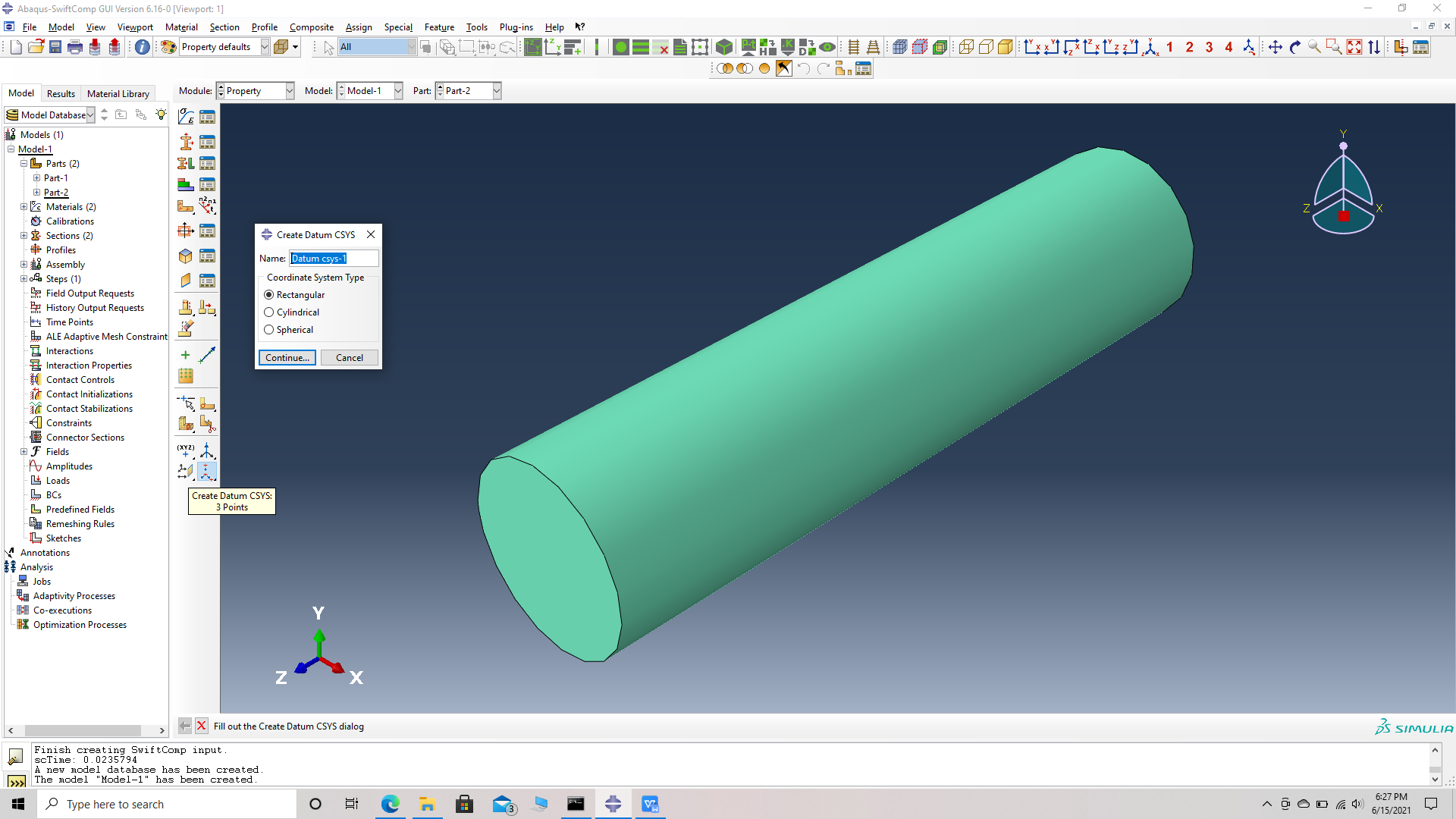 Create datum CSYS
 Choose a point as origin
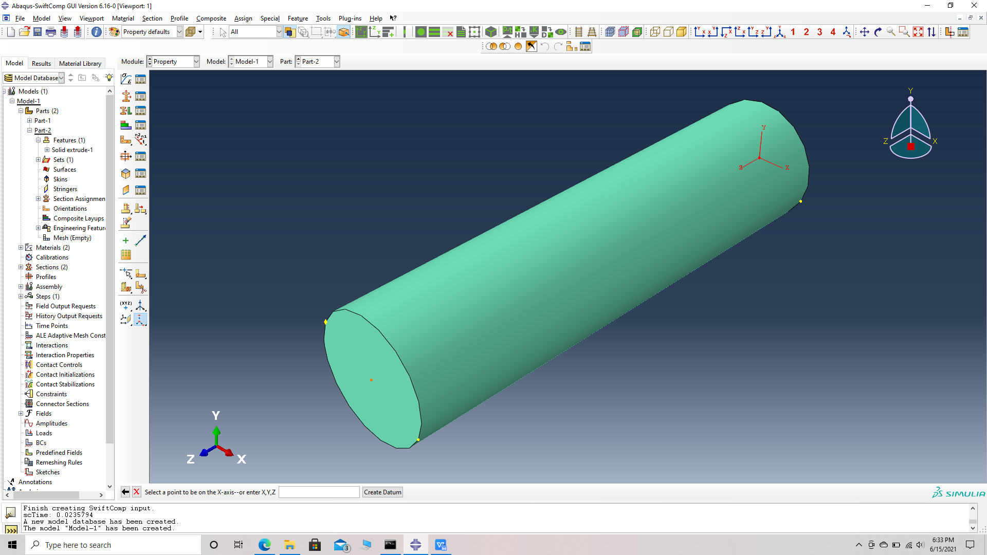 Choose a point on the x axis
 Choose a point on the x-y plane
 New datum
# Step 10. Go to assign material orientation option and select the fiber part -> Done -> Choose Datum CSYS list -> Datum CSYS 1 -> ok -> Make sure the orientation of the fiber material properties match the fiber geometry and select OK.
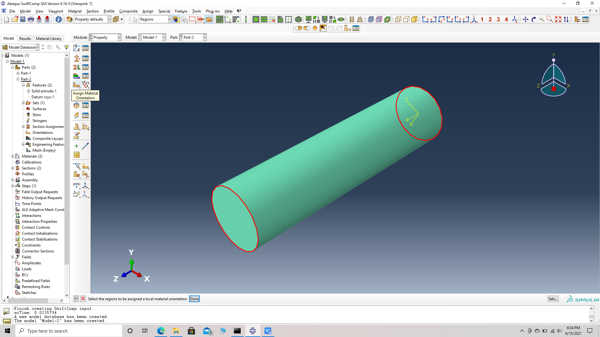 Assign material orientation
 Choose the part and the datum CSYS list at the bottom
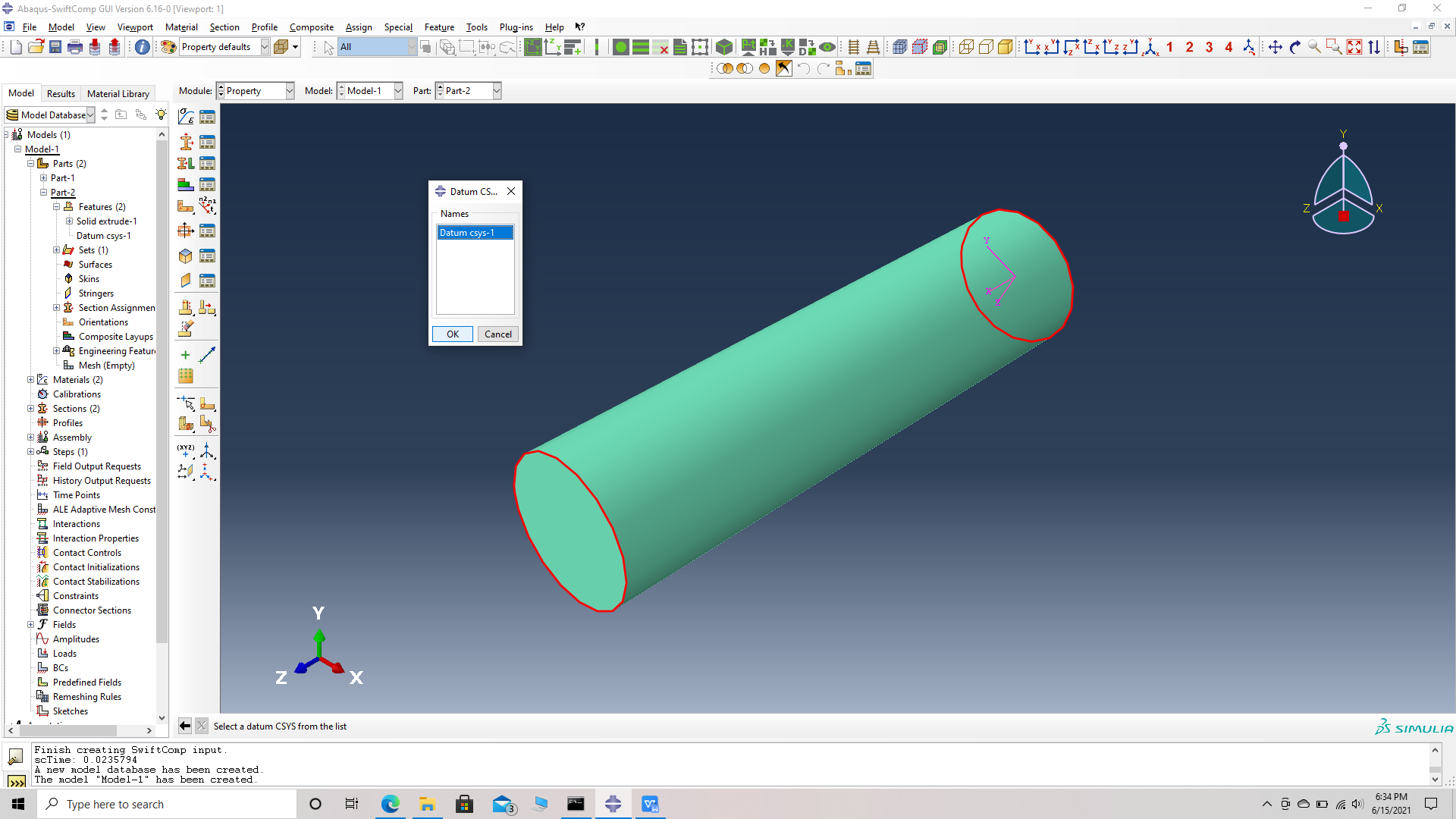 Choose the datum CSYS 1
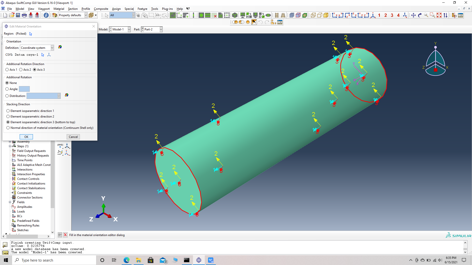 Confirm the orientation
# Step 11. Go to assembly -> create instance -> select both parts, single fiber and matrix unit cell -> Dependent Instance type -> O.K. Use the toggle global transparency option and the view options on the tool bar at the top to see the fiber and matrix together.
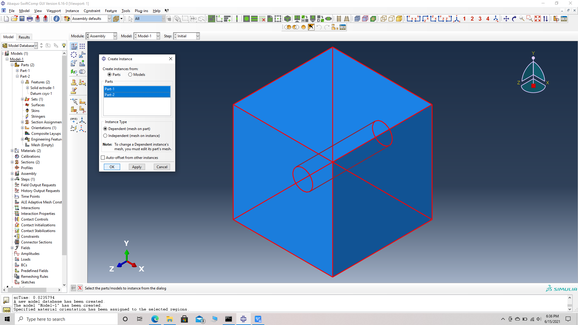 Single fiber assembly
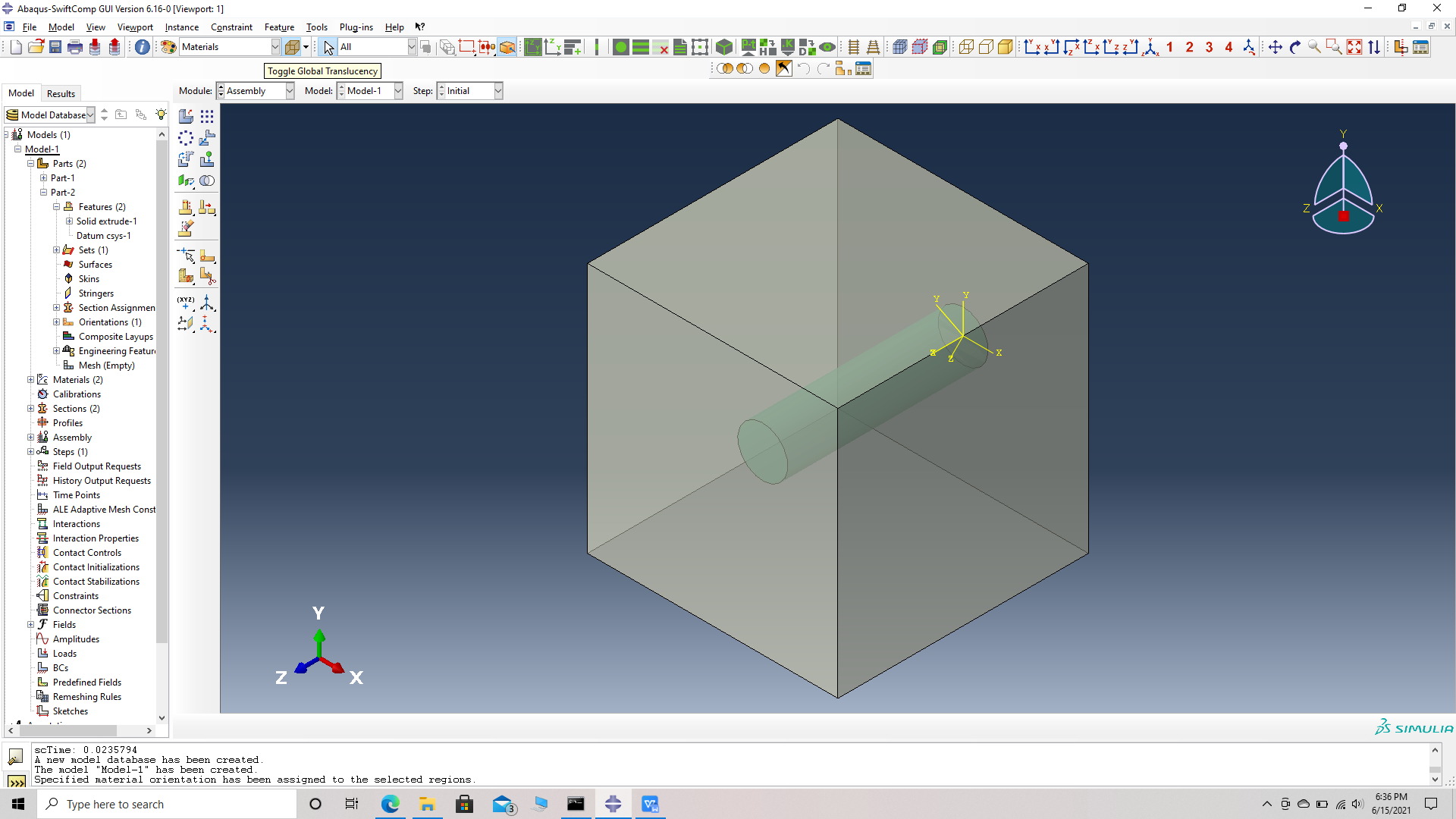 Transparency
# Step 12. We will use the following guidelines to orient the fibers.
i) Translation- Translate instance -> choose the fiber instance -> choose start points for the translation vector -> (0,0,0) -> choose end points for the translation vector -> (x- coordinate, y- coordinate, z- coordinate). The instance can be translated across all three axes simultaneously.
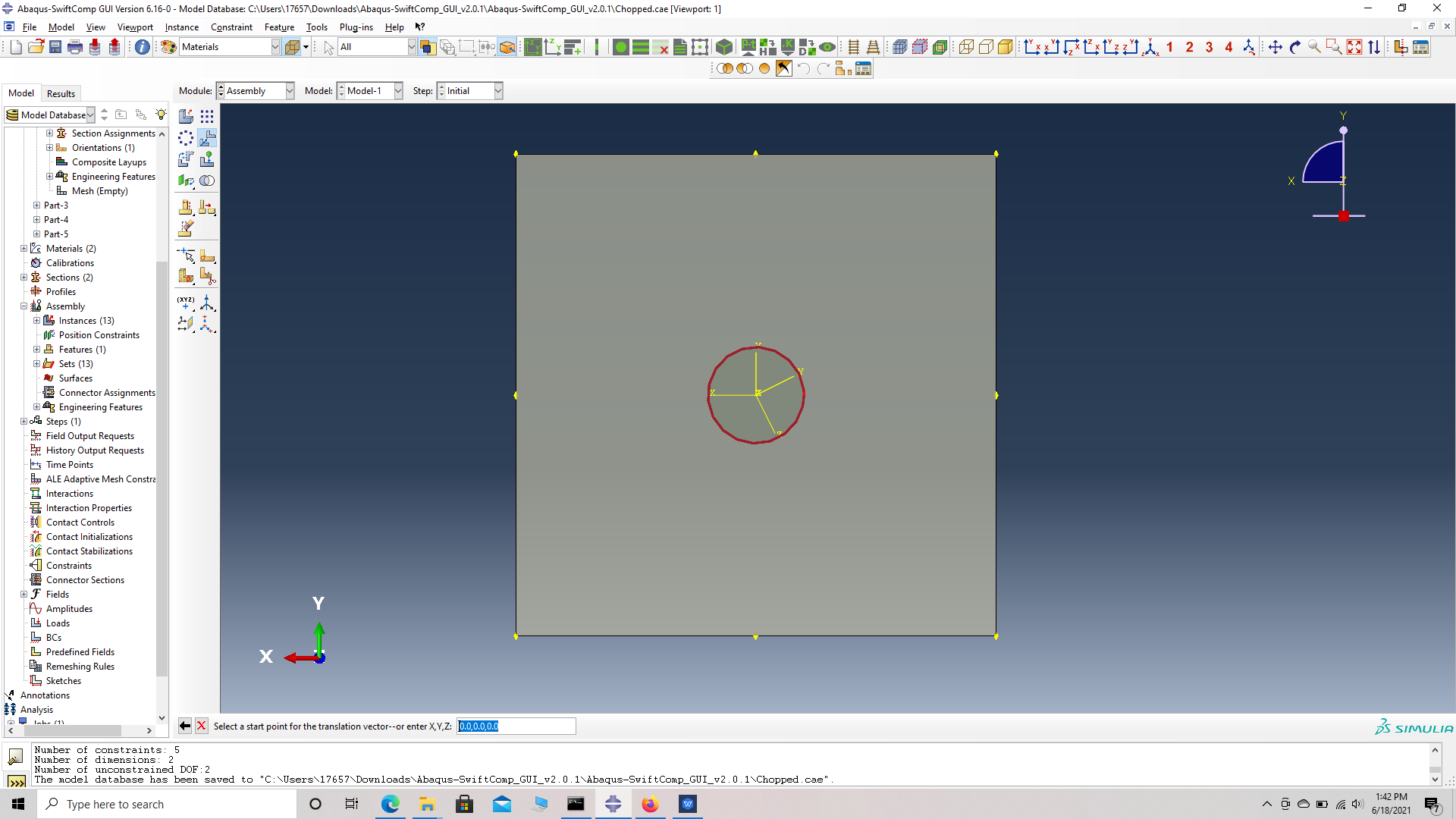
ii)Rotation- Rotate instance -> choose the fiber instance -> choose start points for the axis of rotation -> (0,0,0) -> choose end points for the axis of rotation -> ( positive coordinate for the axis, zero for the other two axes). The instance can be rotated across any one axis at a time. We will rotate along the x axis first followed by the y axis and end with z axis.
# Step 13. Translate the first fiber, Translate instance -> choose the fiber instance -> choose start points for the translation vector -> (0,0,0) -> choose end points for the translation vector -> (2.9, 3.4, 1.0).
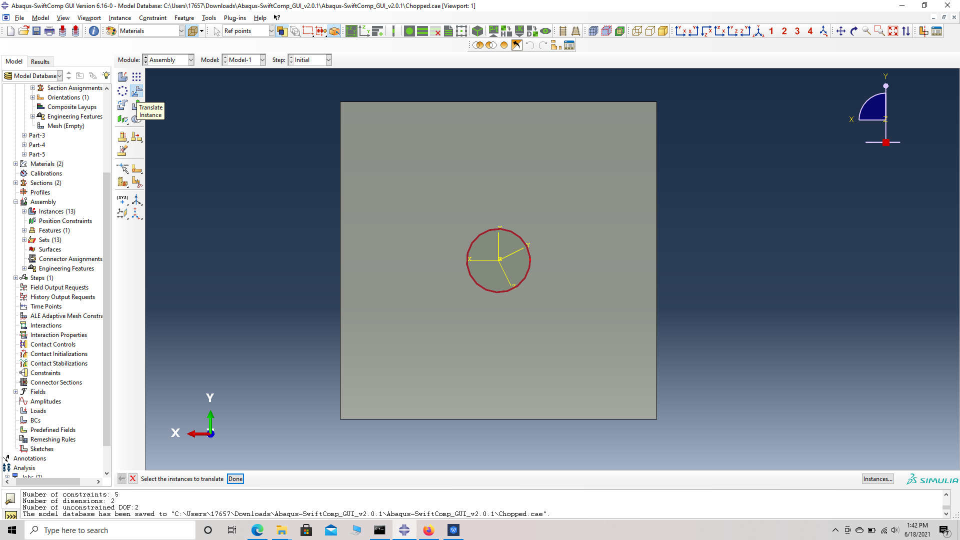 Translate instance
 choose start points for the translation vector
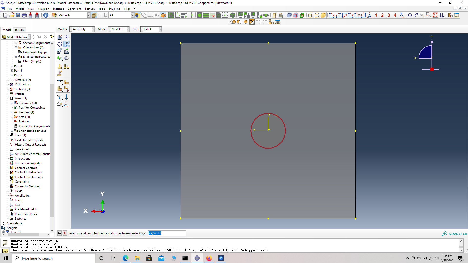 choose end points for the translation vector
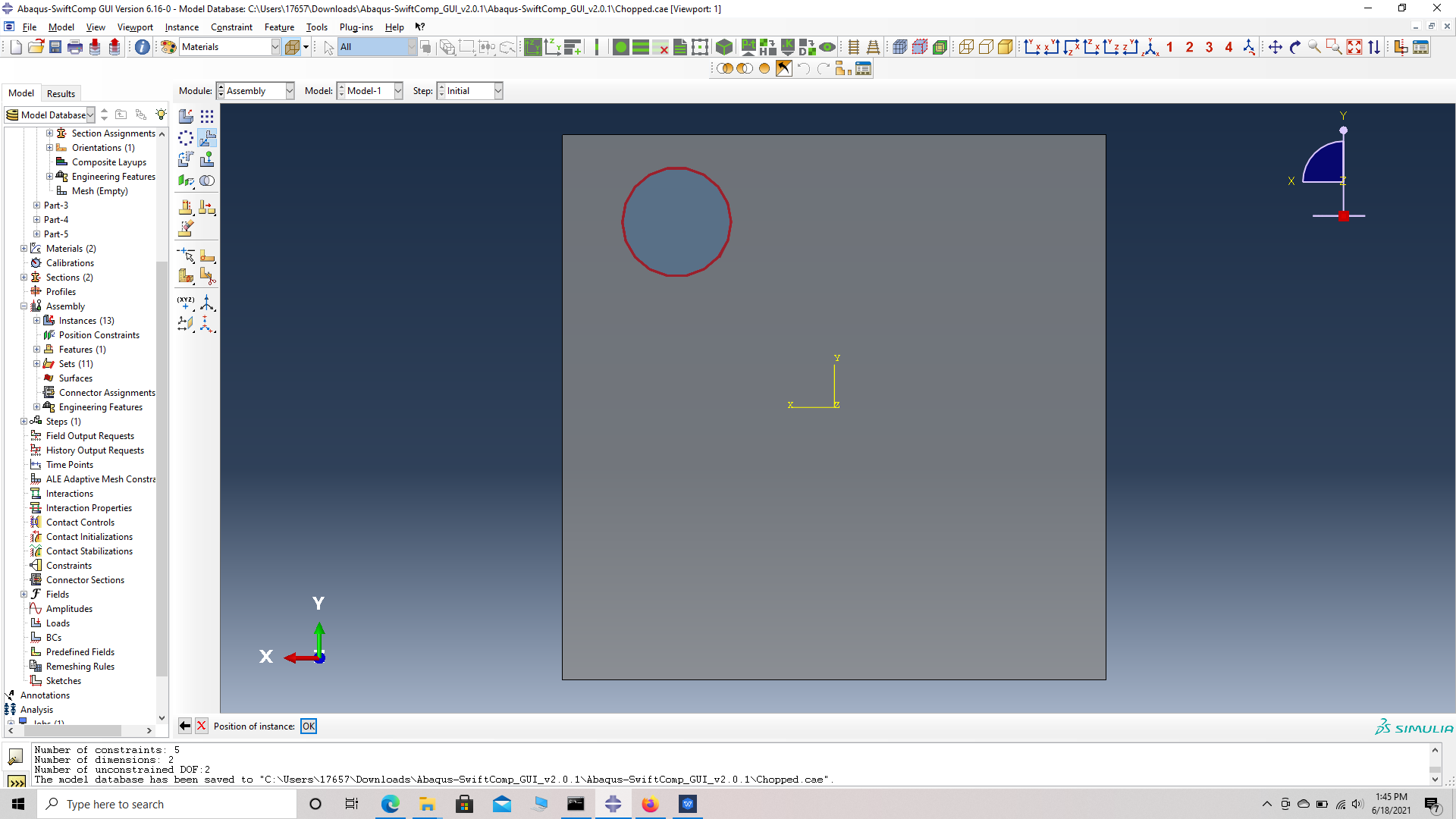 Translated fiber
]]
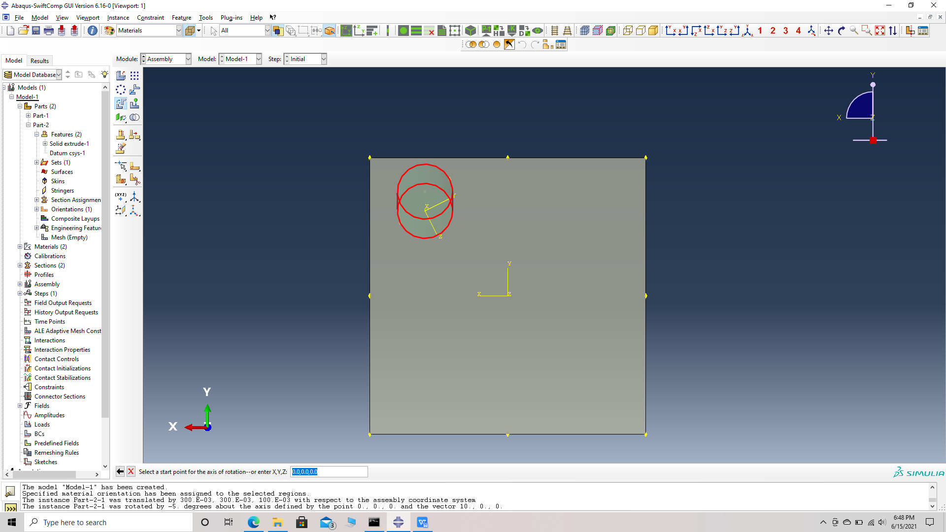
# Step 14. Rotate the first fiber 5 degrees along X followed by 5 degrees along Y. For X, Rotate instance -> choose the fiber instance -> choose start points for the axis of rotation -> (0,0,0) -> choose end points for the axis of rotation -> (1,0,0) -> Angle of rotation -> -3. For Y, Rotate instance -> choose the fiber instance -> choose start points for the axis of rotation -> (0,0,0) -> choose end points for the axis of rotation -> (0,1,0) -> Angle of rotation -> -5.
 Rotate instance
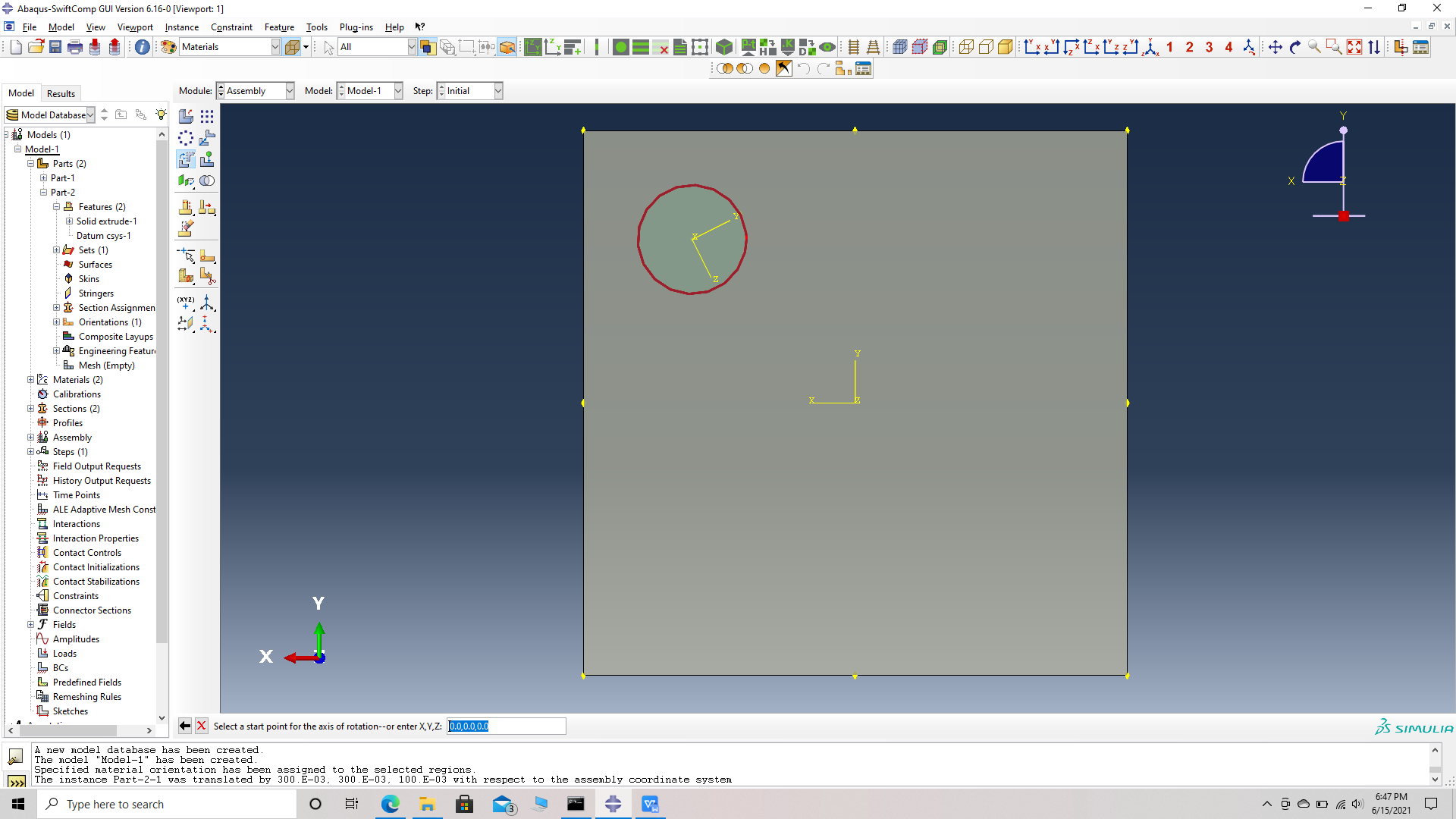 choose start points for the axis of rotation
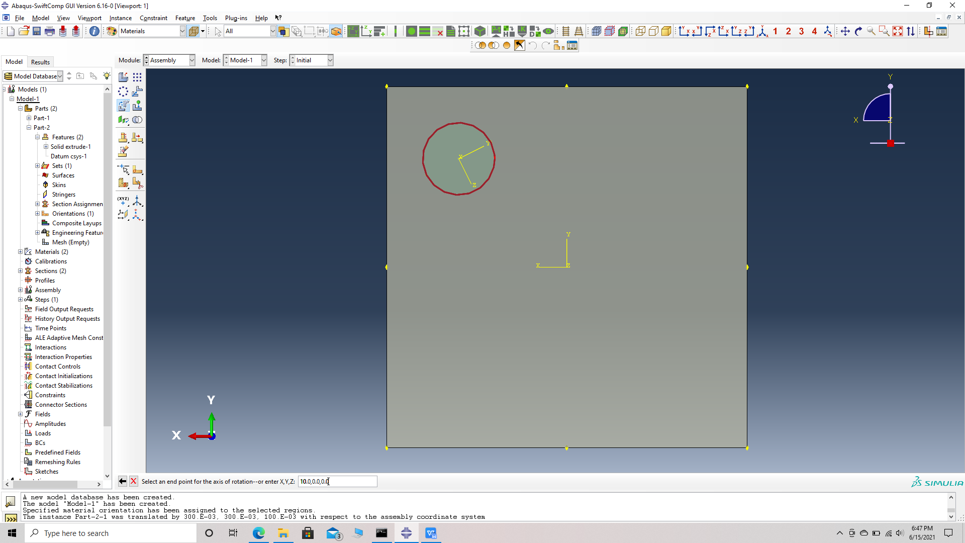 choose end points for the axis of rotation
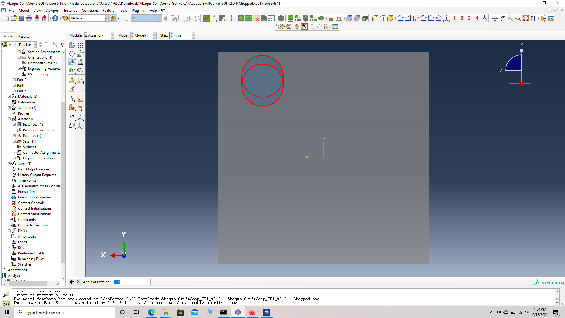 degrees of rotation
 Fiber rotated about X and moving on to Y axis
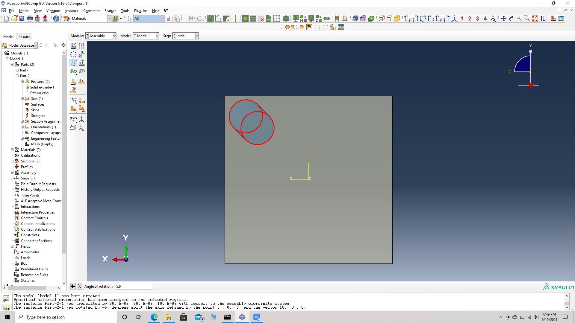 Fiber rotated about X and also Y
# Step 15. Similarly Translate and rotate all fibers according to the table provided.
Fiber orientation
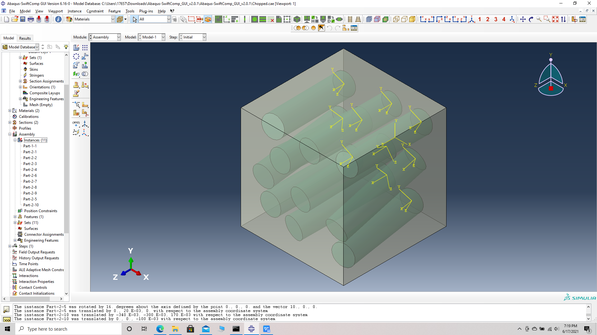 Fibers oriented in matrix unit cell
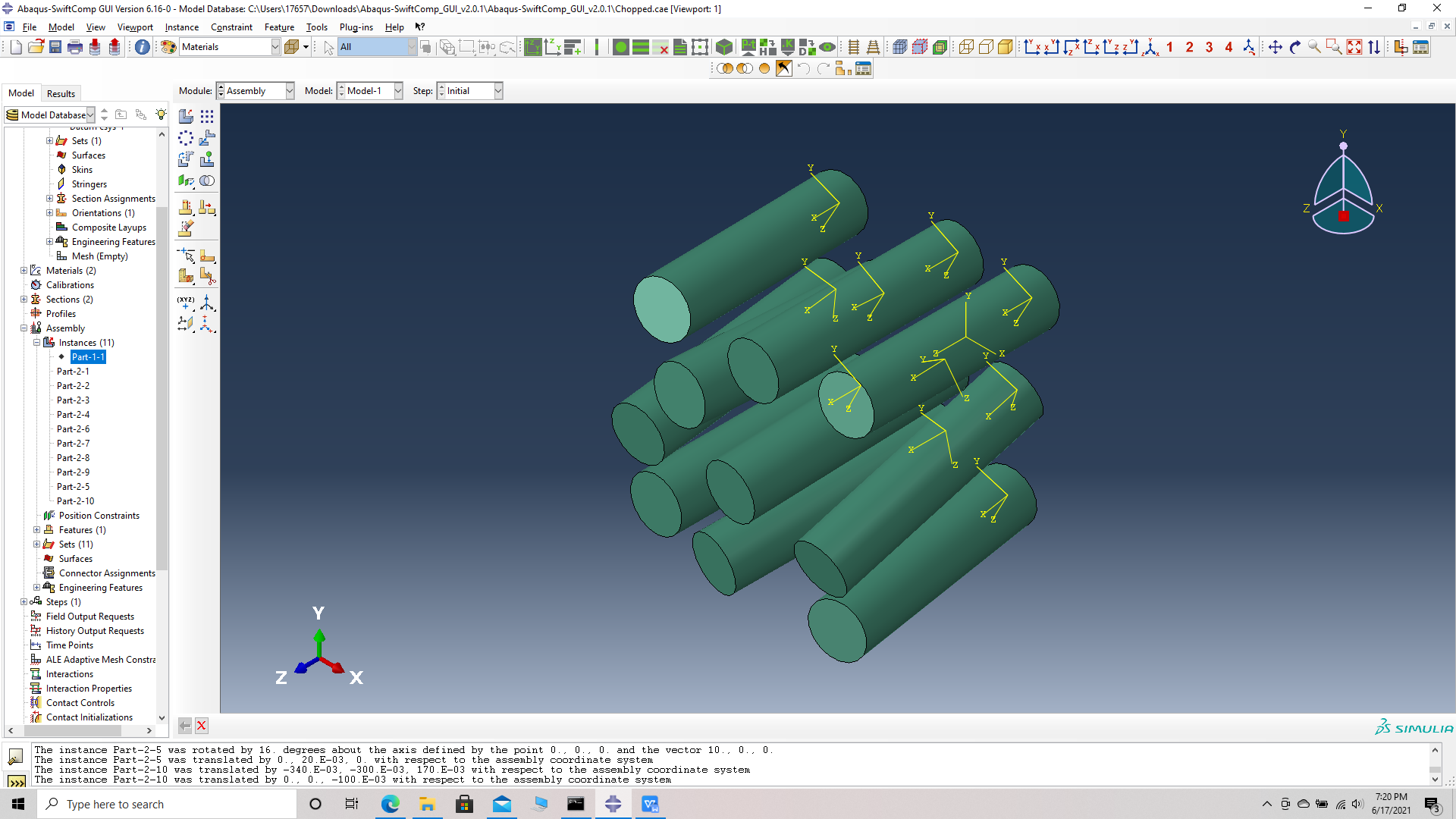 Fibers oriented
# Step 16. Merge the parts, Merge/cut instaces -> Merge geometry -> suppress instances -> retain boundaries -> continue- > select all instances -> Done.
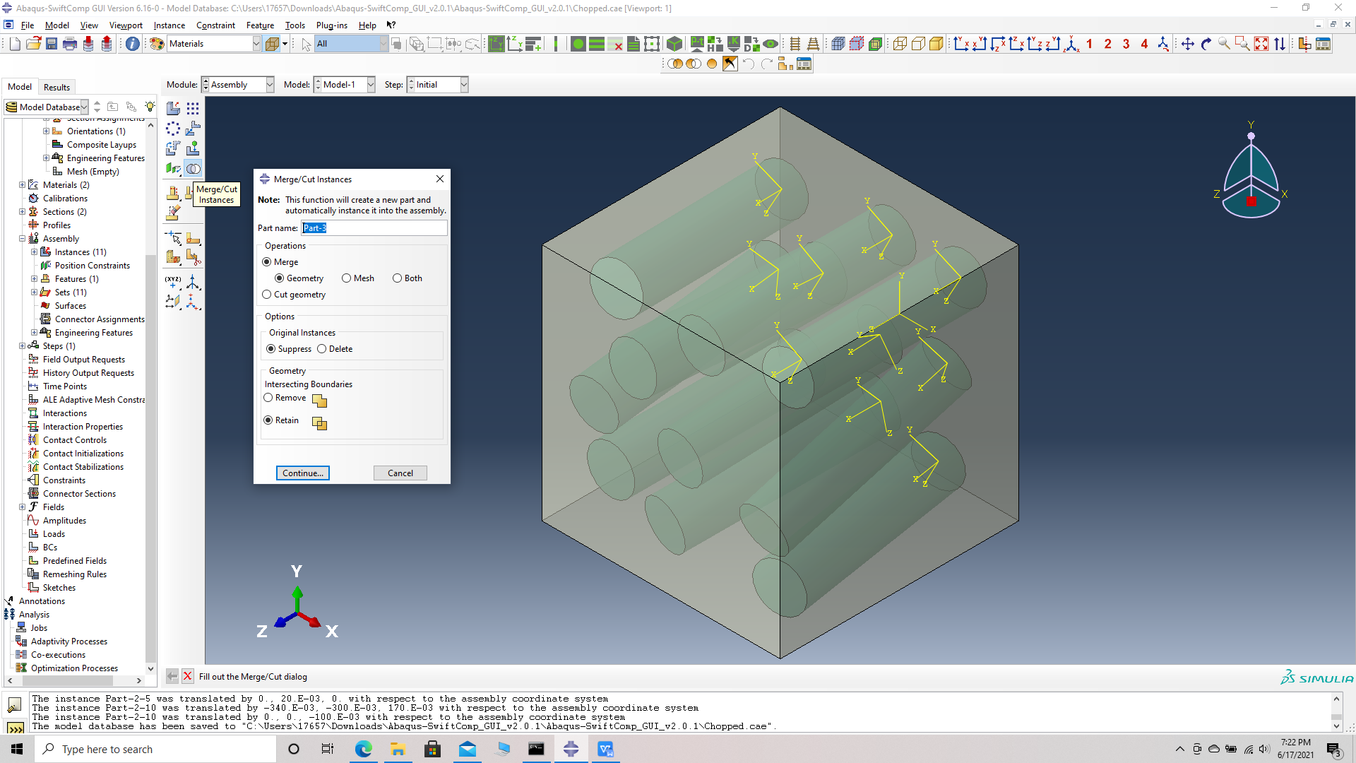 Merge/cut instaces
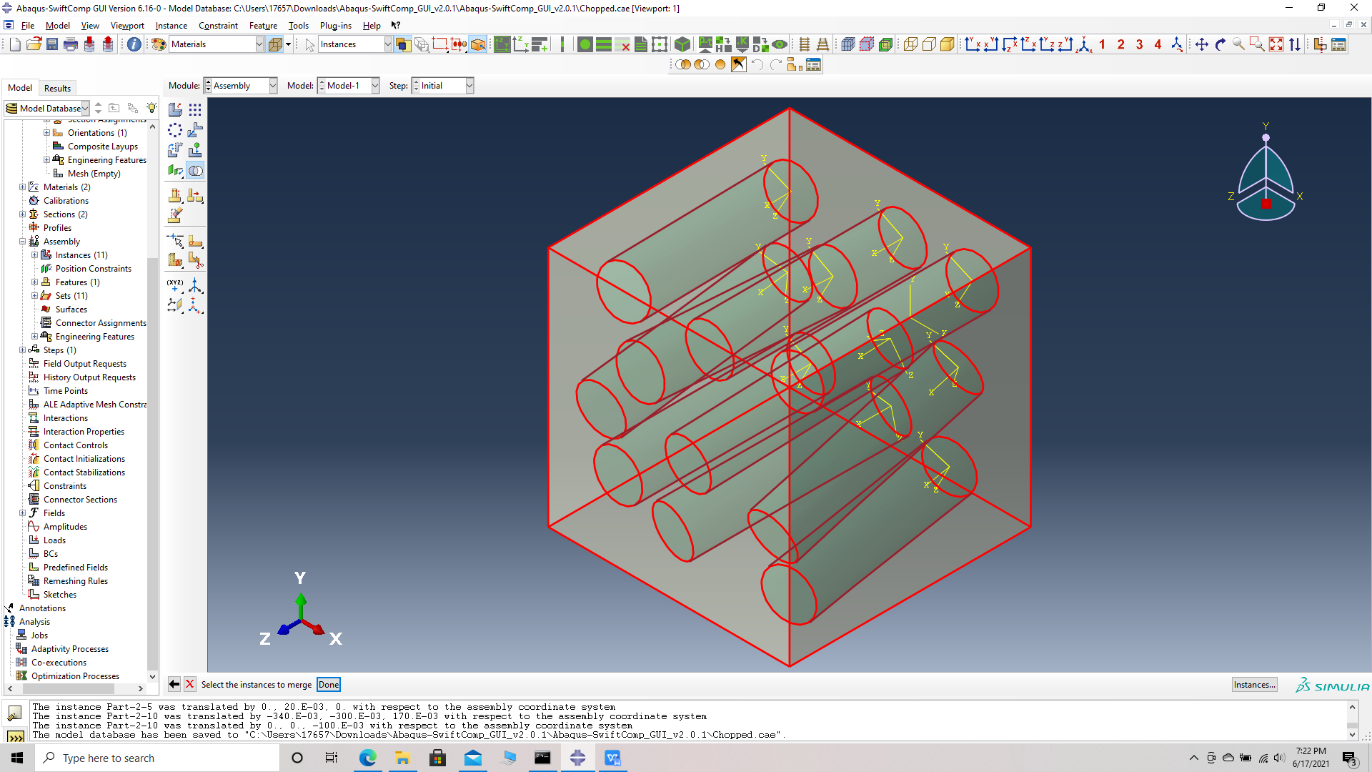 select all instances
# Step 17. Mesh options -> Assign mesh controls -> select part -> Tet mesh-> OK -> Seed part -> Global seed size -> 0.5 -> Mesh part -> OK.
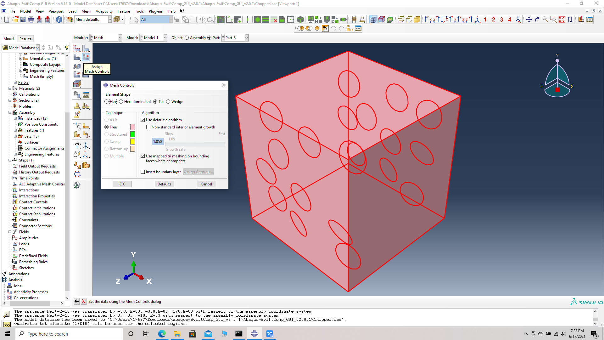 Assign mesh controls -Tet mesh
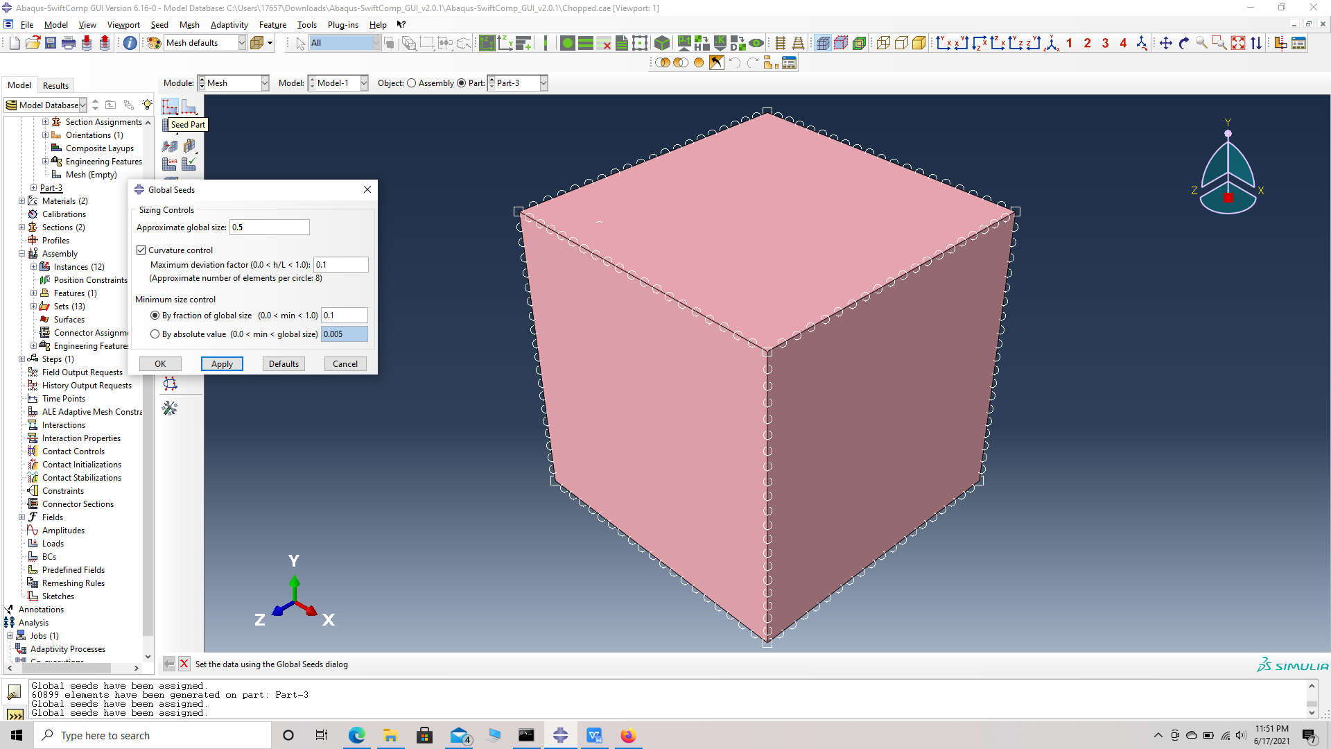 Seed part with Global seed size - 0.5
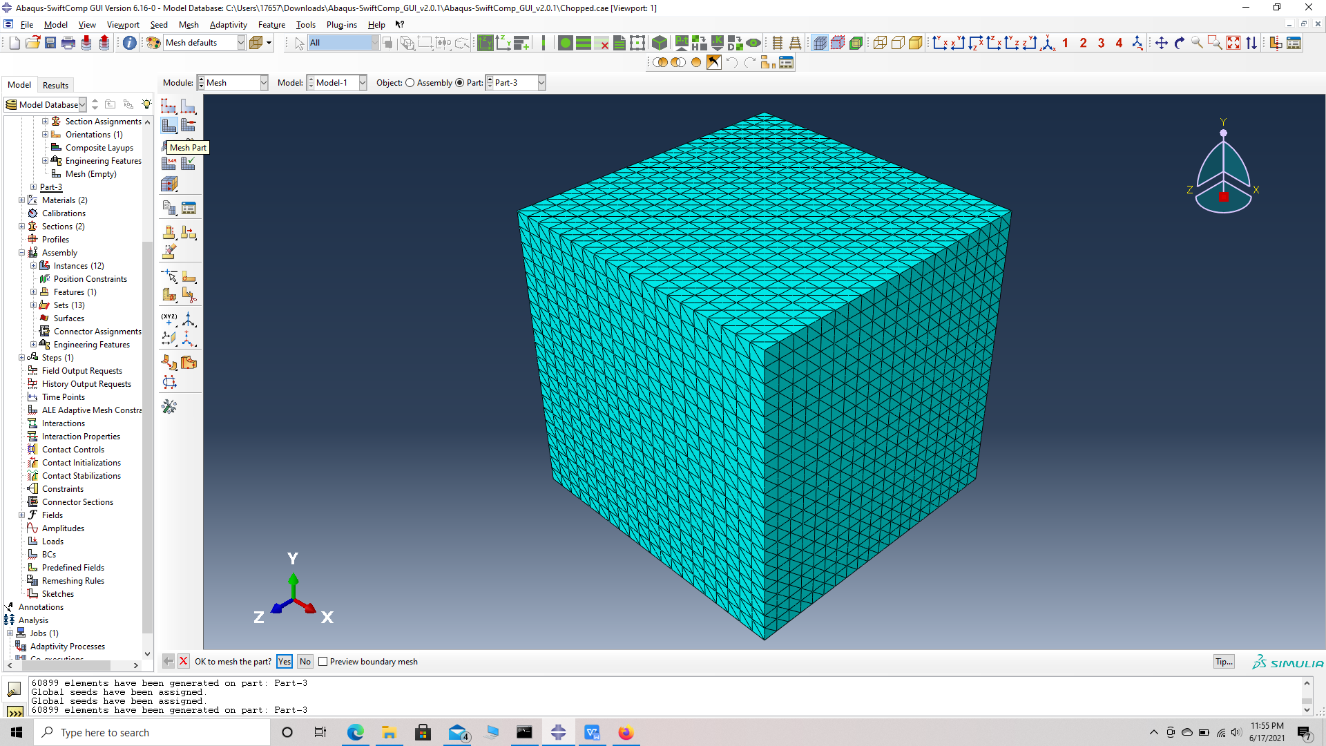 Meshed part
# Step 18. Job -> Create job -> rename Chopped_FRC -> Continue -> Write input.
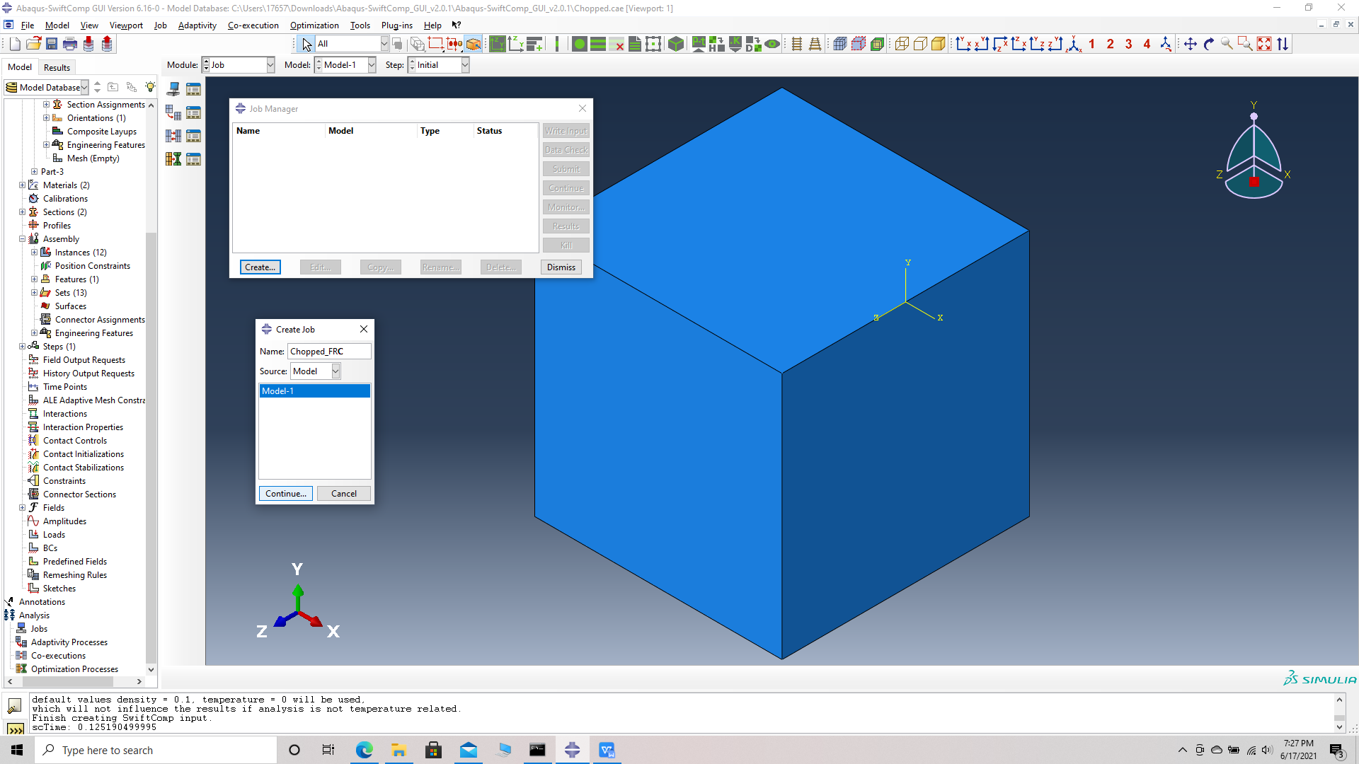 Create job
# Step 19. To the effective Elastic properties. we click on Homogenization and select Elastic in Analysis Type. Homogenize the part preferably as a 3D solid using the Homogenization via input file option to get the final results. The Homogenization via input file option is used when we have to asign material orientations.
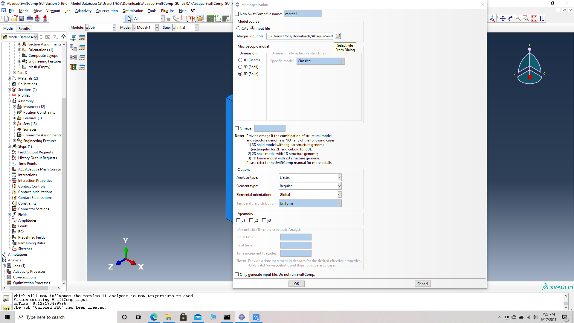 Homogenization
# Step 20. Results the effective Elastic properties of the chopped fiber reinforeced composite are provided in the table below.
(Image(20.1.png, desc=" Results") failed - File not found)