Elastic properties of a chopped fiber reinforced composite
In this example, we want to compute the elastic properties of a chopped fiber reinforced composite 3D SG made of isotropic elastic matrix and transversely isotropic elastic fiber. The MSG solid model is used to predict the effective elastic properties of the SG. We will consider a matrix cell of dimensions 10 mm x 10 mm x 10 mm and ten chopped fibers of radius 1 mm and length 8 mm to have a fiber volume fraction of 0.25. The fiber and matrix properties and the orientation of the individual fibers are given in the tables below.
Software Used
We will use SwiftComp 2.1 and Abaqus CAE with the Abaqus SwiftComp GUI for this tutorial. Abaqus CAE will be used to model the 3D SG while SwiftComp will be used to run the elastic homogenization in the background.
Solution Procedure
The problem is solved in the following steps:
We will first create the matrix cell.
# Step 1. Go to create part -> Create a 3D solid extrusion -> Sketch the cross section as a 10 mm x 10 mm square with the origin at the center. Extrude the part to a length of 10 mm so the origin is at the center of one side. This will help in the assembly.
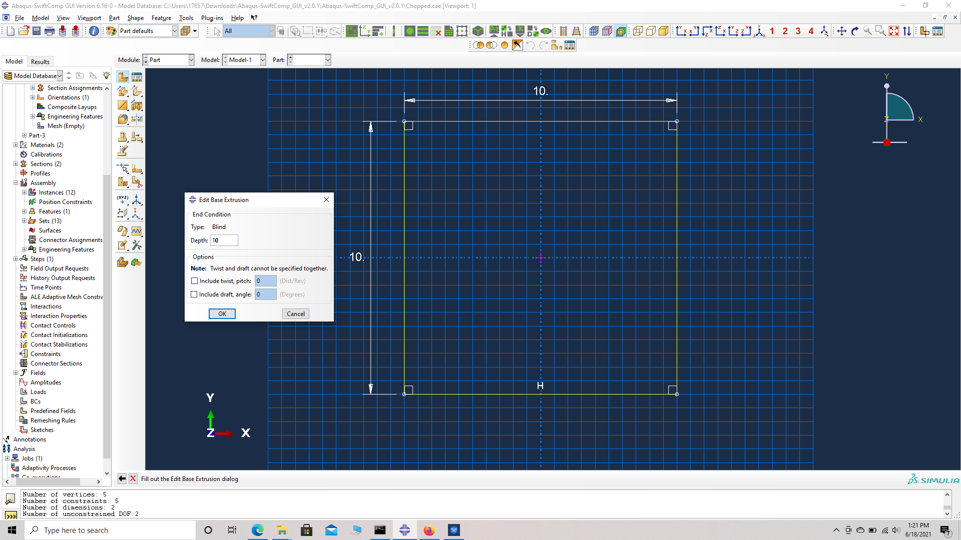 Part dimensions
 Part Geometry
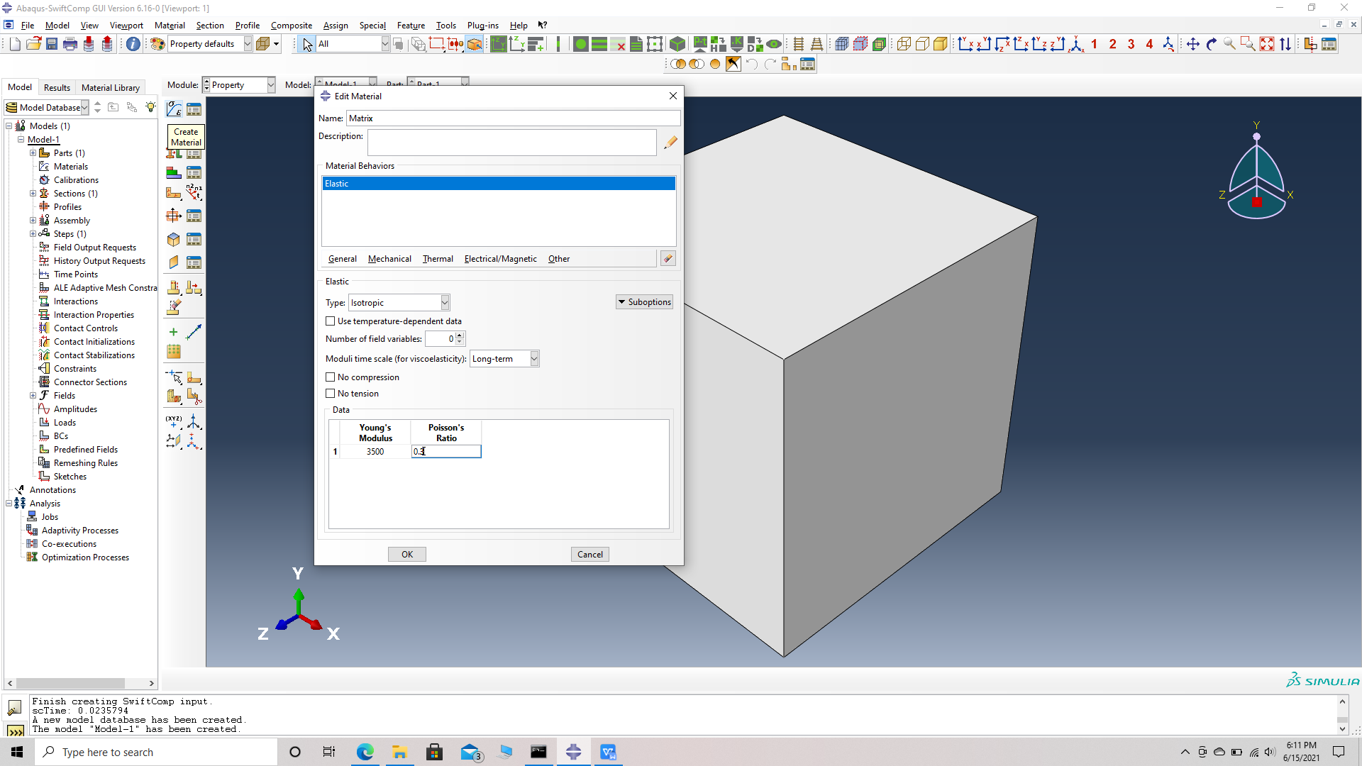
# Step 2. Enter the material properties for the model. First we need to choose the material properties from the matrix property table. Within the Materials section of Abaqus CAE, we create a elastic isotropic material called “Matrix” and add the corresponding properties.
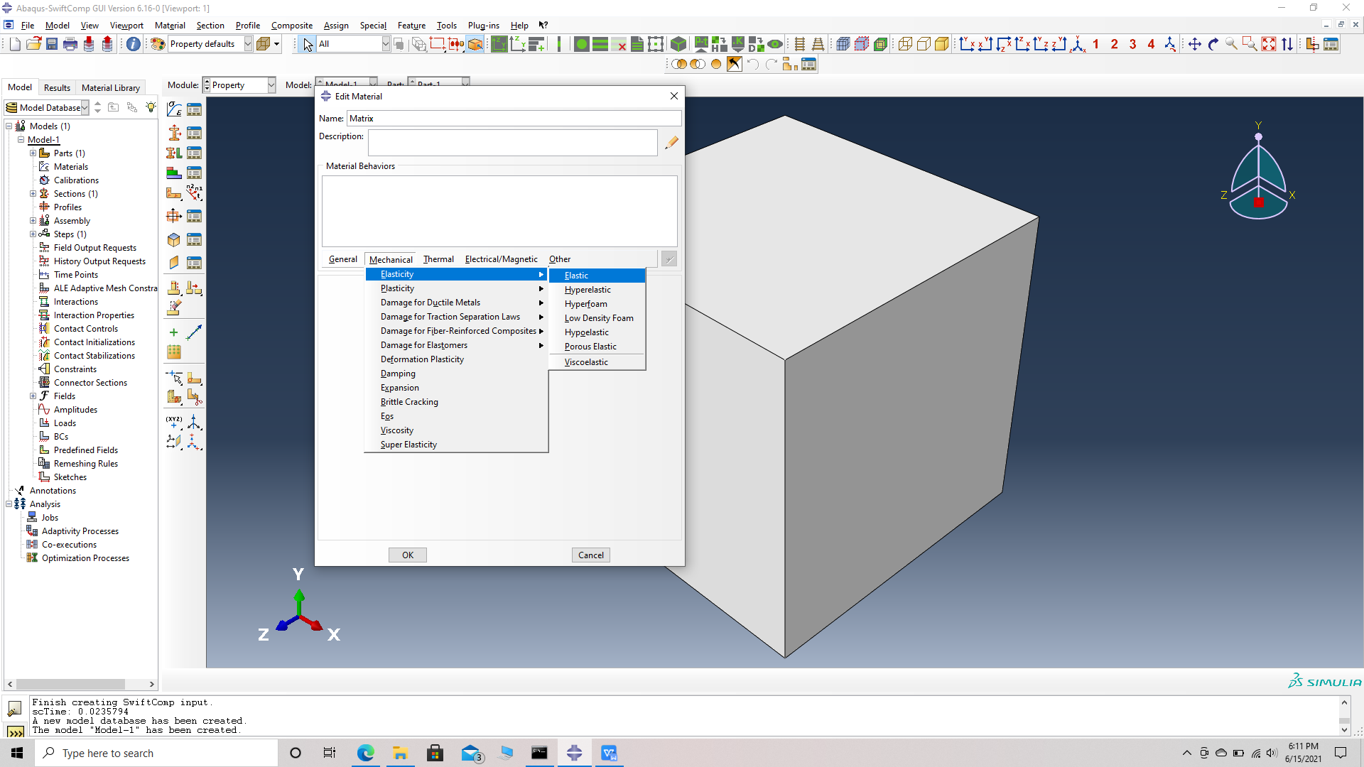 Material properties
 Material properties
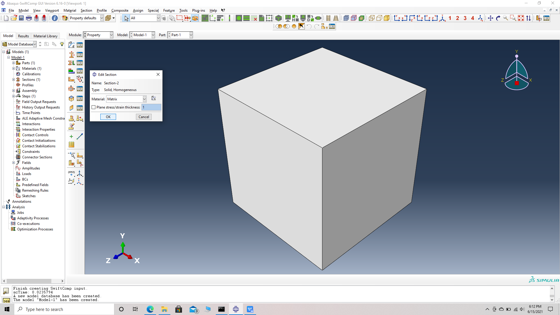
# Step 3. Create a homogeneous section, Section 1 for the matrix using the create section option.
![]() Create a section, Section 1
Create a section, Section 1
 Assiging the material Matrix
# Step 4. Assign the section , Section 1 for the matrix cell using the assign section option. Name the set as Set-111 to differentiate different sets for different parts. Abaqus automatically assigns set- name for all parts as Set -1.
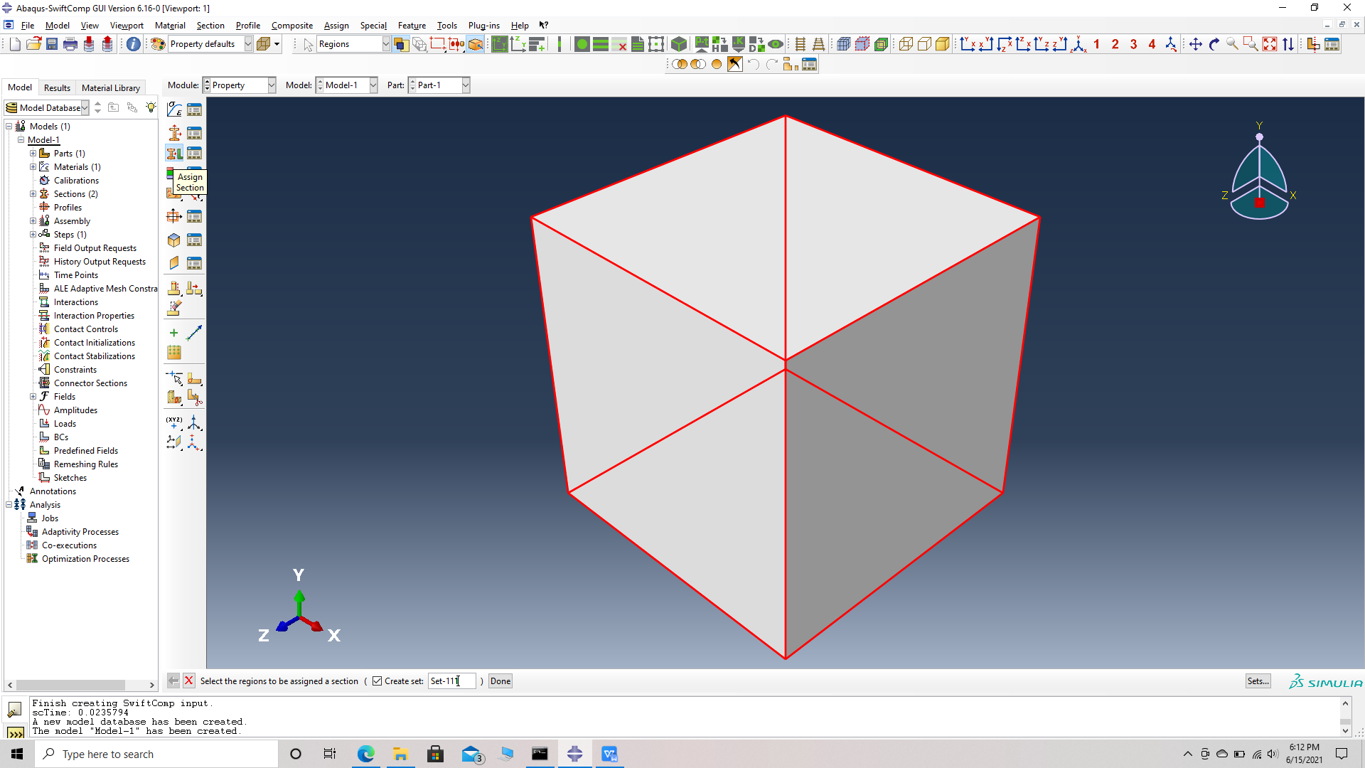 Assign a set renamed as Set 111
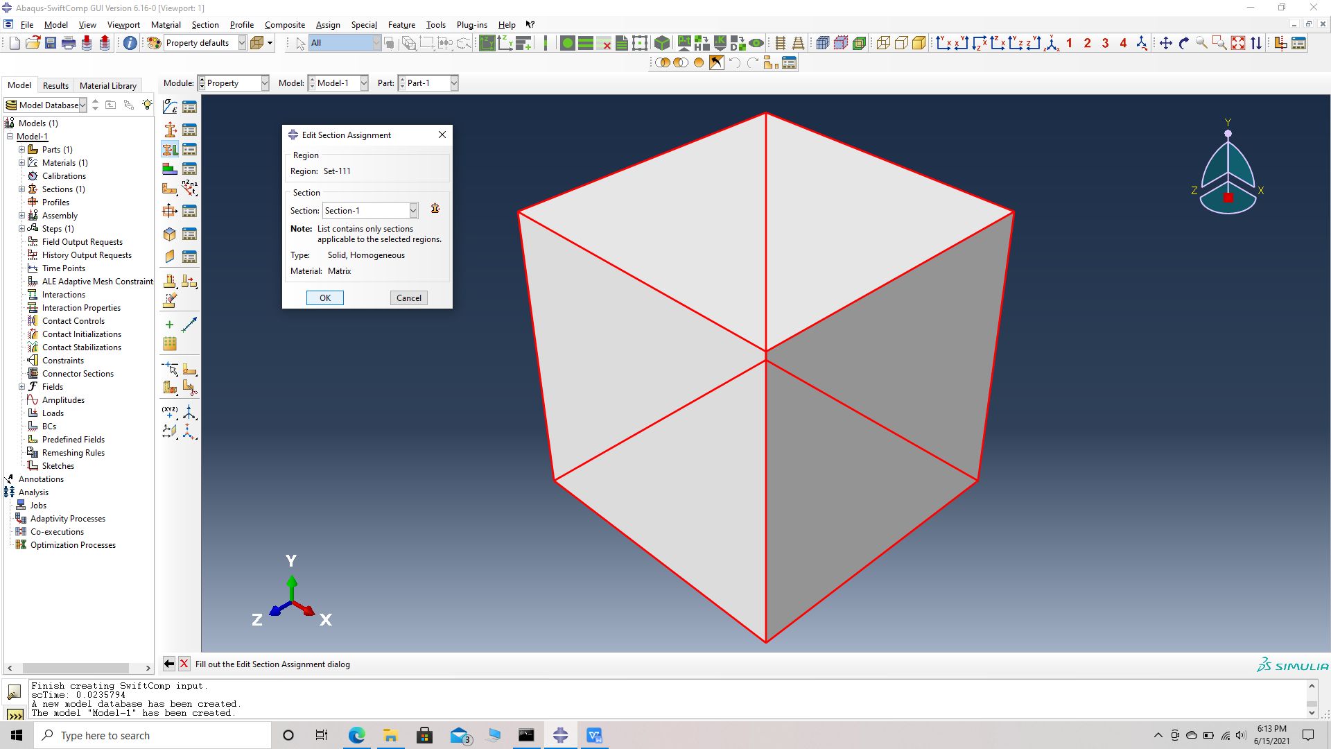 Assiging the Section 1 for Set 111
We will first create the chpped fiber
# Step 5. Go to create part -> Create a 3D solid extrusion -> Sketch the cross section as a circle of radius 1 mm with the origin at the center. Extrude the part to a length of 8 mm so the origin is at the center of one side. This will help in the assembly.
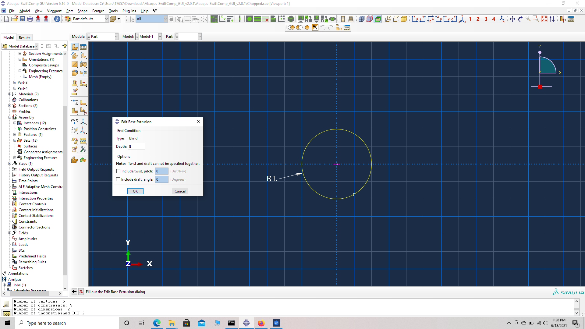 Part dimensions
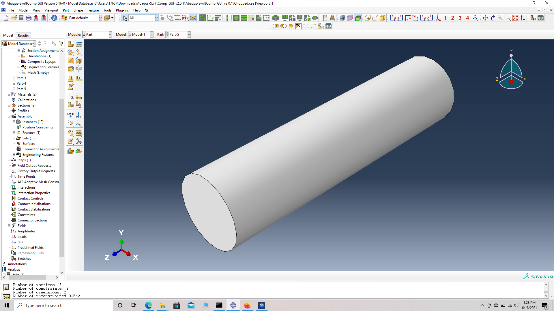 Part Geometry
# Step 6. Enter the material properties for the model. First we need to choose the material properties from the matrix property table. Within the Materials section of Abaqus CAE, we create a elastic isotropic material called “Matrix” and add the corresponding properties.
Material properties
Material properties
# Step 3. Create a homogeneous section, Section 1 for the matrix using the create section option.
![]() Create a section, Section 1
Create a section, Section 1
Assiging the material Matrix
# Step 4. Assign the section , Section 1 for the matrix cell using the assign section option. Name the set as Set-111 to differentiate different sets for different parts. Abaqus automatically assigns set- name for all parts as Set -1.
Assign a set renamed as Set 111
Assiging the Section 1 for Set 111
References
 # ref 1
 # ref 2